Kia Sportage: Oil Cooler | Oil Pressure Switch
Repair procedures
Removal
1. Loosen the drain plug, and drain the coolant. Remove the radiator cap to speed draining.
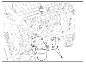
2. Disconnect the oil cooler coolant hoses (A).
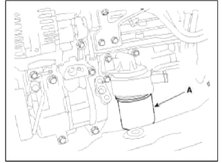
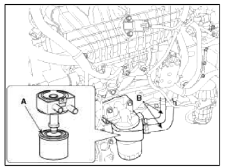
З. Remove the oil filter (A).
4. Loosen the mounting bolt (A) and remove the oil cooler assembly (B).
Installation
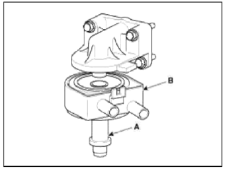
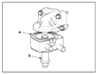
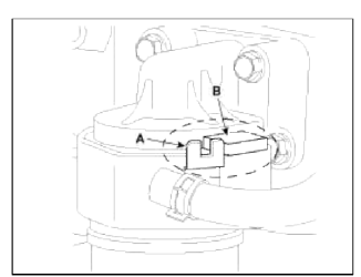
1. Apply a light coat of engine oil to the oil cooler packing surface (A), and then install the oil cooler with fix bolt (B).
Tightening torque: 44.1 ~ 53.9 N.m (4.5 ~ 5.5 kgf.m, 32.5 ~ 39.8 lb-ft)
CAUTION
Fix position of oil cooler stopper (A) where oil cooler resists on ladder frame stopper (B).
2. Apply a light coat of engine oil to the oil filter packing surface (A), and then install the oil filter.
Tightening torque: 11.8 ~ 15.7 N.m (1.2 ~ 1.6 kgf.m, 8.7 ~ 11.6 lb-ft)
3. Connect the oil cooler coolant hoses (B).
4. Fill the radiator with coolant and check for leaks.
Oil Pressure Switch
Repair procedures
Inspection
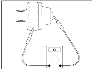
1. Check the continuity between the terminal and the body with an ohmmeter.
If there is no continuity, replace the oil pressure switch.
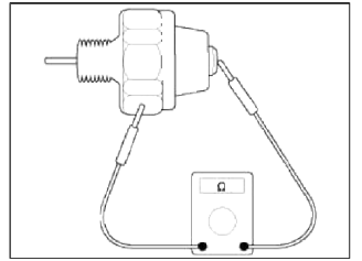
2. Check the continuity between the terminal and the body when the fine wire is pushed. If there is continuity even when the fine wire is pushed, replace the switch.
3. If there is no continuity when a 50kPa (0.50kgf/cm2,7.25psi) is applied through the oil hole, the switch is operating properly.
Check for air leakage. If air leaks, the diaphragm is broken. Replace it.
READ NEXT:
 Intake Manifold
Components and
Components Location
Components
Intake manifold
assembly
Electronic throttle body
Intake manifold stay
Intake manifold gasket
Repair procedures
Removal and Inst
SEE MORE:
General Information
Specifications
Specifications
Tightening Torques
Special Service Tools
Special Service Tools
Fuse/relay panel description
Inside the fuse/relay panel covers, you
can find the fuse/relay label describing
fuse/relay name and capacity.
NOTICE
Not all fuse panel descriptions in this
manual may be applicable to your vehicle.
It is accurate at the time of printing.
When you inspect the fuse panel in your
vehicle,
Content
- Home
- Kia Sportage - Fifth generation (NQ5) - (2022-2026) - Owner's Manual
- Kia Sportage - Second generation (JEKM) (2005-2015) - Body Workshop Manual
- Kia Sportage Third generation (SL) - (2011-2016) - Service and Repair Manual
- Sitemap
- Top articles
