Kia Sportage: Output Speed Sensor
Description and Operation
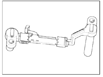
Description
The output speed sensor is a vital unit that measures the rate of rotation of the transaxle's turbine shaft and output shaft, and delivers the readings to the TCM. The sensor provides critical input data that's used in feedback control, damper clutch control, gear setting control, line pressure control, clutch activation pressure control, and sensor fault analysis.
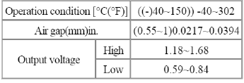
Specifications
Specifications
Type: Hall effect sensor
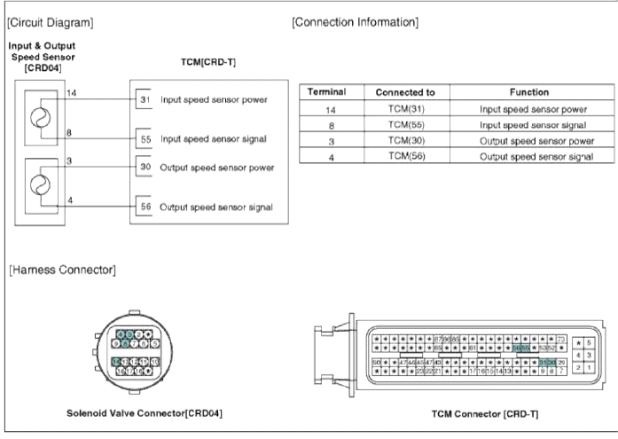
Schematic Diagrams
Circuit Diagram
Troubleshooting
Signal Waveform
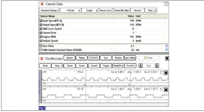
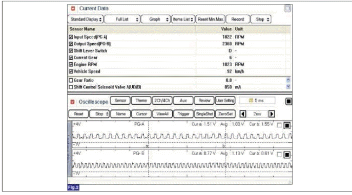
Fig 1) Input/Output speed sensor at low speed Fig 2) Input/Output speed sensor at high speed
Repair procedures
Inspection
1. Check signal waveform of Input & output speed sensor using the GDS.
Specification: Refer to "Signal Wave Form" section.
Removal
1. Remove the battery and the battery tray. (Refer to "Charging system" in EE group.)
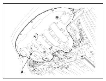
2. Remove the under cover (A).
Tightening torque: 19.6 ~ 24.5 N.m (2.0 ~ 2.5 kgf.m, 14.5 ~ 18.1 lb-ft)
3. Replace new gasket and the ping after draining the automatic transaxle fluid by removing the drain ping. (Refer to "Hydraulic system (Fluid)" in this group)
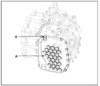
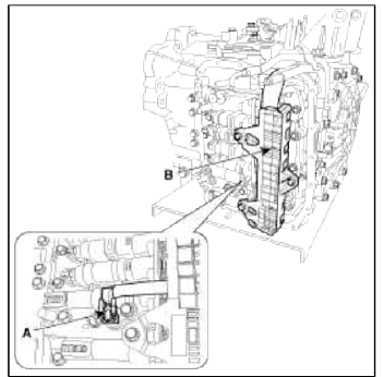
4. Remove the valve body cover (A) and eyebolt (B).
Tightening torque:
(A) 13.8 ~ 14.7 N.m (1.3 ~ 1.5 kgf.m, 9.4 ~ 10.8 lb-ft)
(B) 34.3 ~ 44.1 N.m (3.5 ~ 4.5 kgf.m, 25.3 ~ 32.6 lb-ft)
CAUTION
Always replace the gasket of the eyebolt use new one whenever loosening eyebolt.
NOTE
Remove installation bolts in the engine compartment first and then remove others under the vehicle.
5. Remove the plate and the detent spring (A) after removing the bolt.
Tightening torque: 24.5 ~ 35.3 N.m (2.5 ~ 3.6 kgf.m, 18.1 ~ 26.0 lb-ft)
6. Remove the bolt (3ea) after disconnecting the solenoid valve connector (B) and the oil temperature sensor connector (A).
Tightening torque: 9.8 ~ 11.8 N.m (1.0 ~ 1.2 kgf.m, 7.2 ~ 8.7 lb-ft)
CAUTION
Be careful not to damage the harness lock connector.
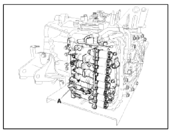
7. Remove the valve body assembly (A).
Tightening torque: 9.8 ~ 11.8 N.m (1.0 ~ 1.2 kgf.m, 7.2 ~ 8.7 lb-ft)
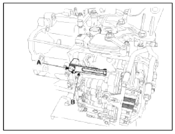
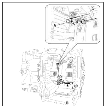
8. Disconnect the input & output speed sensor connector (A).
9. Remove the input & output speed sensor (B) after removing the bolts(2ea).
Tightening torque: 9.8 ~ 11.8 N.m (1.0 ~ 1.2 kgf.m, 7.2 ~ 8.7 lb-ft)
Installation
1. Installation is the reverse of removal.
NOTE
After replacement or reinstallation procedure of the valve body assembly, must perform procedures below.
- Continue to apply liquid gasket at application points at the valve body cover with Ø2.5mm (0.0984in.) thickness.
Liquid gasket Part name : Threebond 1281B or LOCTITE FMD-546
- Adding automatic transaxle fluid. (Refer to "Hydraulic system (Fluid)" in this group)
READ NEXT:
 Torque Converter Control Solenoid Valve (T/CON_VFS) | 26 Brake Control Solenoid Valve (26/B_VFS)
Description and Operation
Description
Torque converter control solenoid valve (T/CON_VFS) is attached to the valve body. This variable force solenoid valve directly controls the hydraulic pre
Line Pressure Control Solenoid Valve | 35R Clutch Control Solenoid Valve (35R/C_VFS)
Description and Operation
Description
Line pressure control solenoid valve is attached to the valve body. This variable force solenoid valve directly controls the hydraulic pressure inside th
SEE MORE:
Front Wiper Motor
Components and
Components Location
Component Location
Cap
Nut
Wiper arm & blade
Clip
Cowl top cover
Bolt
Wiper motor & linkage assembly
Wiper motor connector
Repair procedures
Removal
1. Remove the windshield wiper arm and blade after
Components and Components Location | Steering Column and Shaft
Components
Steering wheel
Steering column
ECU
Motor
Steering gear box
MDPS Circuit Diagram
Harness Connector
Battery
Battery -
Battery +
Vehicle
IGN
-
-
Content
- Home
- Kia Sportage - Fifth generation (NQ5) - (2022-2026) - Owner's Manual
- Kia Sportage - Second generation (JEKM) (2005-2015) - Body Workshop Manual
- Kia Sportage Third generation (SL) - (2011-2016) - Service and Repair Manual
- Sitemap
- Top articles
