Kia Sportage: Radiator
Components and Components Location
Components
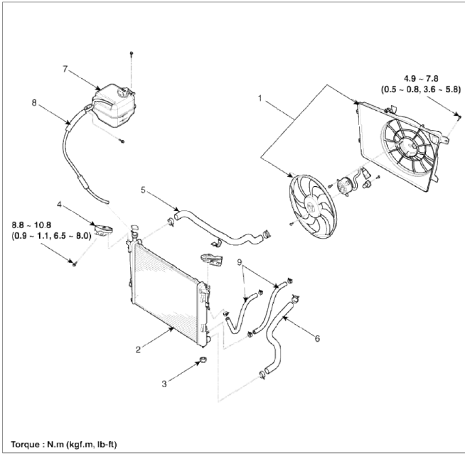
- Cooling fan assembly
- Radiator assembly
- Mounting insulator
- Radiator mounting bracket
- Radiator upper hose
- Radiator lower hose
- Reservoir tank
- Over flow hose
- ATF cooler hoses
Repair procedures
Inspection
Radiator Cap Testing
1. Remove the radiator cap, wet its seal with engine coolant, and then install it on a pressure tester.
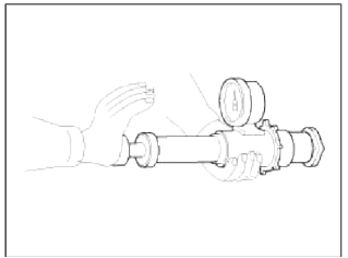
2. Apply a pressure of 93.16 ~ 122.58kPa (0.95 ~ 1.25kgf/cm2, 13.51 ~ 17.78psi).
3. Check for a drop in pressure.
4. If the pressure drops, replace the cap.
Radiator Leakage Test
1. Wait until engine is cool, then carefully remove the radiator cap and fill the radiator with engine coolant, then install it on the pressure tester (A).
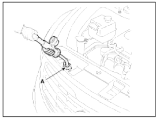
2. Apply a pressure tester to the radiator and apply a pressure of 93.16 ~ 122.58kPa (0.95 ~ 1.25kgf/cm2, 13.51 ~ 17.78psi).
3. Inspect for engine coolant leaks and a drop in pressure.
4. Remove the tester and reinstall the radiator cap.
NOTE
Check for engine oil in the coolant and/or coolant in the engine oil.
Removal and Installation
1. Disconnect the battery terminals. (Refer to Engine and transaxle assembly in this group)
2. Remove the air cleaner assembly and intercooler inlet/outlet hose & pipes. (Refer to Engine and transaxle assembly in this group)
3. Remove the battery and battery tray. (Refer to Engine and transaxle assembly in this group)
4. Remove the radiator grill upper guard (A). (Refer to BD group)
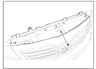
5. Remove the radiator upper cover (A).
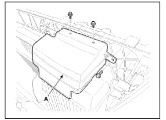
6. Remove the horn bracket (A). (Refer to BE group)
7. Remove the radiator front air guard (B).
8. Seperate the condenser (C) from the radiator.
9. Disconnect the over flow hose (A) from the radiator.
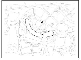
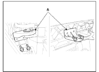
10. Remove the radiator mounting bracket assemblies (A).
Tightening torque: 8.8 ~ 10.8 N.m (0.9 ~ 1.1 kgf.m 6.5 ~ 8.0 lb-ft)
11. Disconnect the fan motor connector (A).
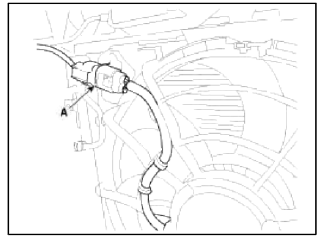
12. Remove the cooling fan assembly (A).
Tightening torque: 4.9 ~ 7.8 N.m (0.5 ~ 0.8 kgf.m, 3.6 ~ 5.8 lb-ft)
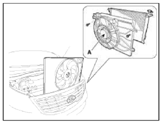
13. Remove the under cover. (Refer to Engine and transaxle assembly in this group)
14. Loosen the drain plug, and drain the engine coolant. Remove the radiator cap to drain with speed.
15. Disconnect the radiator upper hose (A) and lower hose (B).
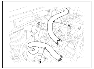
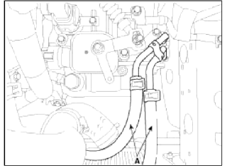
16. Disconnect the ATF cooler hoses. (Refer to AT group)
17. Remove the radiator assembly (A).
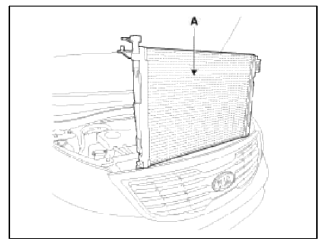
18. Installation is the reverse order of removal.
19. Fill the radiator with coolant and check for leaks.
NOTE
- Bleed air from the cooling system.
- Start engine and let it run until it warms up. (Until the radiator fan operates 3 or 4 times.)
- Turn off engine. Check the coolant level and add coolant if needed. This will allow trapped air to be removed from the cooling system.
- Put the radiator cap on tightly, then run engine again and check for leaks.
READ NEXT:
 Water pump
Components and Components Location
Components
Water pump pulley
Water pump sub assembly
Water pump gasket
Water pump cover
Water pump cover gasket
O-ring
Water inlet pipe
Wa
Thermostat
Repair procedures
Removal and Installation
NOTE
Disassembly of the thermostat would have an adverse effect, causing a
lowering of cooling efficiency. Do not
remove the thermostat, even if the en
SEE MORE:
Components and Components Location | Rear Wiper Motor
Component Location
Rear wiper motor assembly
Head cap
Rear wiper motor mounting bolt
Rear wiper motor mounting hole
Pad cap
Hexagonal nut
Cover
Rear wiper arm & blade
Rear wiper arm nut
Rear Wiper Motor
Repair procedures
Inspect
Explanation of scheduled maintenance items
Engine oil and filter
The engine oil and filter should be
changed at the intervals specified in the
maintenance schedule. If the vehicle is
being driven in severe conditions, more
frequent oil and filter changes are
required.
Drive belts
Inspect all drive belts for evidence of
cuts, cracks,
Content
- Home
- Kia Sportage - Fifth generation (NQ5) - (2022-2026) - Owner's Manual
- Kia Sportage - Second generation (JEKM) (2005-2015) - Body Workshop Manual
- Kia Sportage Third generation (SL) - (2011-2016) - Service and Repair Manual
- Sitemap
- Top articles
