Kia Sportage: Thermostat
Repair procedures
Removal and Installation
NOTE
Disassembly of the thermostat would have an adverse effect, causing a lowering of cooling efficiency. Do not remove the thermostat, even if the engine tends to overheat.
1. Drain engine coolant so its level is below thermostat.
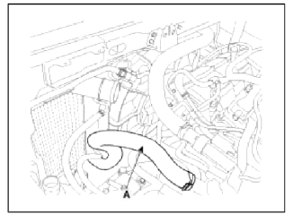
2. Disconnect the radiator lower hose (A).
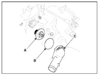
3. Remove water inlet fitting (C), gasket (B) and thermostat (A).
Tightening torque: 7.8 ~ 11.8N.m (0.8 ~ 1.2kgf.m, 5.8 ~ 8.7lb-ft)
4. Installation is reverse order of removal.
CAUTION
- Install the thermostat with the jiggle valve upward.
- When assembling the thermostat, place the thermostat on the housing with a protrusion of thermostat matching with a groove of the housing and install the gasket and inlet fitting. Be careful the thermostat doesn't get out of the groove on the housing.
5. Fill the engine coolant.
6. Start the engine and check for leaks.
7. Recheck the coolant level
Inspection
1. Immerse the thermostat in water and gradually heat the water.
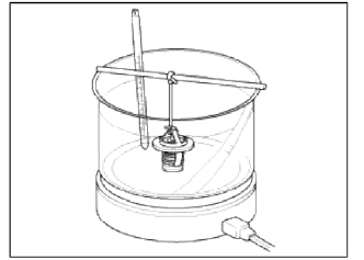
2. Check the valve opening temperature.
Valve opening temperature: 82 +- 1.5ºC (179.6 +- 2.7ºF)
Full opening temperature: 95ºC (203ºF)
If the valve opening temperature is not as specified, replace the thermostat.
3. Check the valve lift.
Valve lift: 8mm (0.3in.) or more at 95ºC (203ºF)
If the valve lift is not as specified, replace the thermostat.
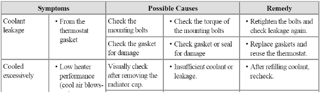
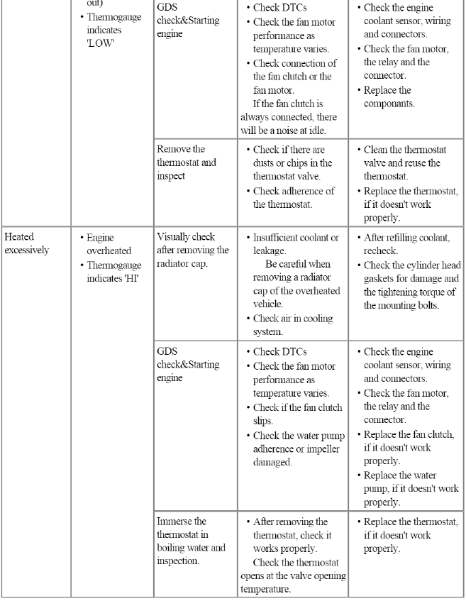
Troubleshooting
Troubleshooting
READ NEXT:
 Engine Oil
Repair procedures
Oil And Filter Replacement
CAUTION
Prolonged and repeated contact with mineral oil will result in the
removal of natural fats from the skin, leading to
dryness, irritation
Balance Shaft & Oil Pump
Components and
Components Location
Components
Balance shaft & oil pump
assembly
Balance shaft chain tensioner
Balance shaft chain
Balance shaft chain sprocket
Balance shaft
SEE MORE:
Engine Oil
Repair procedures
Oil And Filter Replacement
CAUTION
Prolonged and repeated contact with mineral oil will result in the
removal of natural fats from the skin, leading to
dryness, irritation and dermatitis. In addition, used engine oil contains
potentially harmful contaminants which
m
Vehicle load limit
The vehicle load limit is displayed on
the tire and loading information
label on the driver's door.
Tire and loading information
label
The label located on the driver's
door sill gives the original tire size,
cold tire pressures recommended
for your vehicle, the number of people
tha
Content
- Home
- Kia Sportage - Fifth generation (NQ5) - (2022-2026) - Owner's Manual
- Kia Sportage - Second generation (JEKM) (2005-2015) - Body Workshop Manual
- Kia Sportage Third generation (SL) - (2011-2016) - Service and Repair Manual
- Sitemap
- Top articles
