Kia Sportage: Rail Pressure Sensor (RPS)
Description and Operation
Description
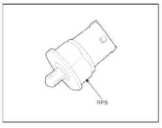
Rail Pressure Sensor (RPS) is installed on the delivery pipe and measures the instantaneous fuel pressure in the delivery pipe. The sensing element (Semiconductor element) built in the sensor converts the pressure to voltage signal. By using this signal, the ECM can control correct injection amount and timing and adjusts the fuel pressure with the fuel pressure regulator valve if the target pressure and the actual pressure calculated by the RPS output signal are different.
Specifications
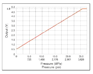
Specifications
Troubleshooting
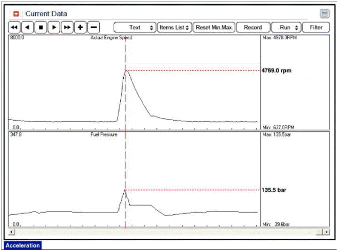
Signal Waveform
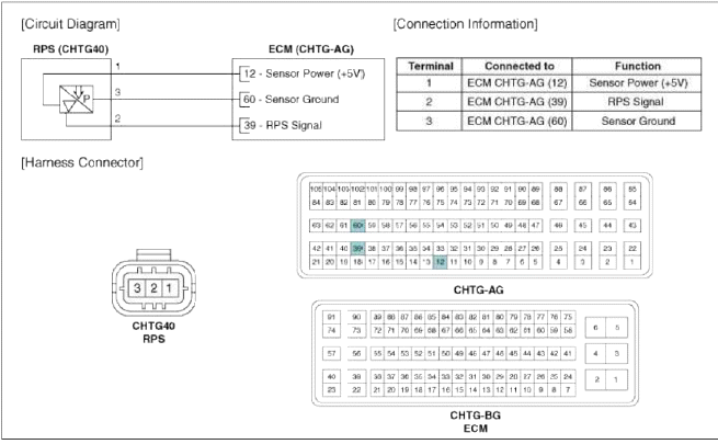
Schematic Diagrams
Circuit Diagram
Repair procedures
Inspection
1. Connect the GDS on the Data Link Connector (DLC).
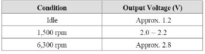
2. Measure the output voltage of the RPS at idle and various engine speed.
Removal
1. Turn the ignition switch OFF and disconnect the battery negative (-) cable.
2. Release the residual pressure in fuel line (Refer to "Release Residual Pressure in Fuel Line" in this group).
CAUTION
When removing the fuel pump relay, a Diagnostic Trouble Code (DTC) may occur. Delete the code with the GDS after completion of "Release Residual Pressure in Fuel Line" work.
3. Remove the intake manifold (Refer to "Intake And Exhaust System" in EM group).
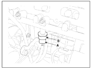
4. Disconnect the rail pressure sensor connector (A), and then remove the sensor (B) from the delivery pipe.
Installation
CAUTION
- Install the component with the specified torques.
- Note that internal damage may occur when the component is dropped. If the component has been dropped, inspect before installing.
1. Installation is reverse of removal.
Rail Pressure Sensor Installation: 18.0 ~ 22.0 N.m (1.8 ~ 2.2 kgf.m, 13.3 ~ 16.2 lb-ft)
READ NEXT:
 CVVT Oil Temperature Sensor (OTS)
Description and
Operation
Description
Continuous Variable Valve Timing (CVVT) system advances or retards the valve
tuning of the intake and exhaust
valve in accordance with the ECM control
Accelerator Position Sensor (APS) | Fuel Tank Pressure Sensor (FTPS)
Description and Operation
Description
Accelerator Position Sensor (APS) is installed on the accelerator pedal module and detects the rotation angle of the accelerator pedal. The APS is one of
SEE MORE:
Battery replacement
The smart key uses a 3 volt lithium battery
which will normally last for several
years.
If you are
unsure how to use or replace
the battery, contact an authorized Kia
dealer.
Detach mechanical key from your
smart key.
Pry open the key cover.
Replace the smart key cover with a
Cleaning the upholstery and interior
trim
Car interior surfaces
Remove dust and loose dirt from interior
surfaces with a whisk broom or a vacuum
cleaner. If necessary, clean interior
surfaces with a mixture of warm water
and mild non-detergent cleaner (test all
cleaners on a concealed area before
use).
Fabric
Remove dust and loose
Content
- Home
- Kia Sportage - Fifth generation (NQ5) - (2022-2026) - Owner's Manual
- Kia Sportage - Second generation (JEKM) (2005-2015) - Body Workshop Manual
- Kia Sportage Third generation (SL) - (2011-2016) - Service and Repair Manual
- Sitemap
- Top articles
