Kia Sportage: RCV Control Solenoid Valve | Canister Close Valve (CCV)
Description and Operation
Description
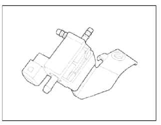
RCV (Recirculation Valve) Control Solenoid Valve is installed on the intercooler inlet pipe and operates the RCV actuator which controls the by-pass passage of the turbocharger compressor.
When the throttle is closed, while the engine is running at cruise rpm (tip-out), the turbocharger boost pressure raises rapidly. The pressure wave strikes a compressor blades causing a knocking noise. To prevent this the ECM opens the recirculation valve which allows excessive boost pressure to vent back to the air cleaner side of the turbocharger compressor.
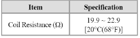
Specifications
Specification

Schematic Diagrams
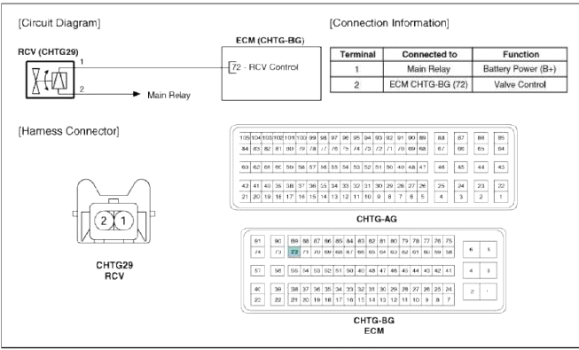
Circuit Diagram
Repair procedures
Inspection
1. Turn the ignition switch OFF.
2. Disconnect the RCV control solenoid valve connector.
3. Measure resistance between the valve terminals 1 and 2.
4. Check that the resistance is within the specification.
Specification: Refer to "Specification"
Removal
1. Turn the ignition switch OFF and disconnect the battery negative (-) cable.
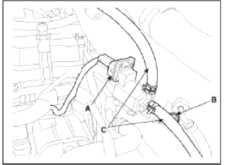
2. Remove the RCV control solenoid valve after disconnect the connector (A), bolt (B) and RCV hose (C).
Installation
CAUTION
- Do not apply oil when hose assembled.
- The hose should be inserted perfectly to nipple.
1. Installation is the reverse order of removal.
RCV Control Solenoid Valve installation bolt: 9.8 ~ 11.8 N.m (1.0 ~ 1.2 kgf.m. 7.2 ~ 8.7 lb-ft)
Canister Close Valve (CCV)
Description and Operation
Description
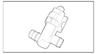
Canister Close Valve (CCV) is installed on the canister ventilation line. It seals evaporative emission control system by shutting the canister from the atmosphere when leakage detecting system operates.
Specifications
Specification
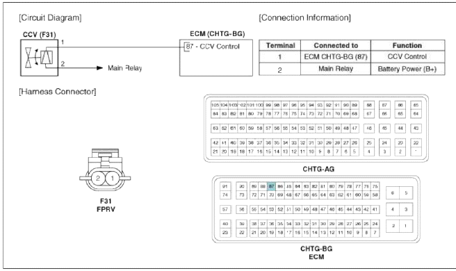
Schematic Diagrams
Circuit Diagram
Repair procedures
Inspection
1. Тurn the ignition switch OFF.
2. Disconnect the CCV connector.
3. Measure resistance between the CCV terminal 1 and 2.
4. Check that the resistance is within the specification.
Specification: Refer to "Specification"
5. Disconnect the vapor hose connected with the canister from the CCV.
6. Connect a vacuum pump to the nipple.
7. Ground the CCV control line and apply battery voltage to the CCV power supply line.
8. Apply vacuum and check the valve operation.
Specification: Vacuum maintained
Removal
1. Turn the ignition switch OFF and disconnect the battery negative (-) cable.
2. Lift the vehicle.
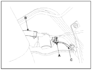
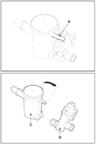
3. Disconnect the canister close valve connector (A).
4. Disconnect the ventilation hose (B, C) from the fuel tank an filter and canister close valve.
5. Remove the fuel tank air filter and canister close valve assembly (A) after removing the mounting nut (B).
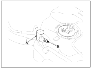
6. Release the lever (A), and then separate the canister close valve (B) from the fuel tank air filter (C) after rotating it in the direction of the arrow in the figure.
Installation
CAUTION
- Install the component with the specified torques.
- Note that internal damage may occur when the component is dropped. If the component has been dropped, inspect before installing.
1. Installation is reverse of removal.
READ NEXT:
 Components and Components Location | Repair procedures
Components Location
Fuel tank
Fuel pump
Fuel filter
Fuel pressure regulator
Canister
Fuel tank air filter
Fuel tank band
Fuel tank pressure sensor (F
SEE MORE:
Components and ComponentsLocation | Removal - Repair procedures
Components (1)
[Hand Type] / [Foot Type]
Parking brake pedal assembly
Front parking brake cable (Foot type only)
Equalizer assembly
Rear parking brake cable
Parking brake lever assembly
Components (2)
[2WD]
Backing plate
Brake shoe
Sh
Rear Seat
Components and Components
Location
Components
Headrest
Headrest guide
Tether anchor garnish
Upper bezel
Rear seat back pad
Latch cover
Rear seat back cover
Armrest board
Rear armrest
Rear seat back frame
Rear seat cushion cover
Rear seat cushion warmer
Rear seat
Content
- Home
- Kia Sportage - Fifth generation (NQ5) - (2022-2026) - Owner's Manual
- Kia Sportage - Second generation (JEKM) (2005-2015) - Body Workshop Manual
- Kia Sportage Third generation (SL) - (2011-2016) - Service and Repair Manual
- Sitemap
- Top articles
