Kia Sportage: Rear Axle Assembly
Rear Hub - Carrier
Components and Components Location
Components
(2WD) / (4WD)
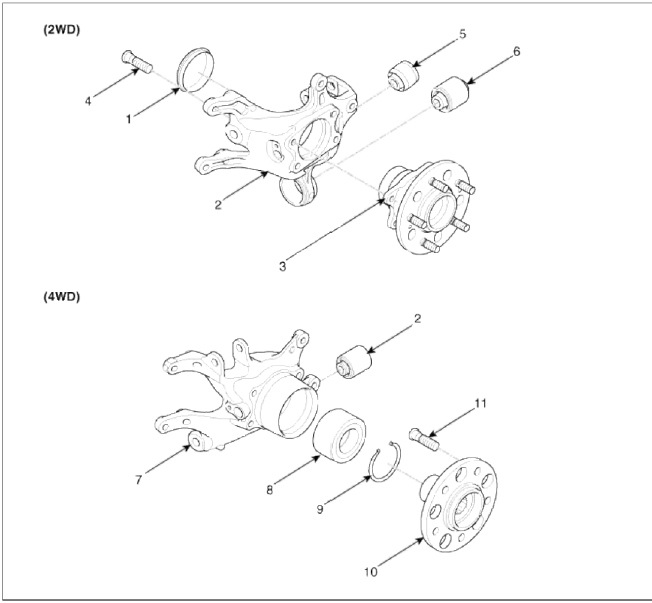
- Hub cover
- Carrier assembly
- Hub & bearing assembly
- Hub mounting bolt
- Bushing
- Bushing
- Carrier assembly
- Bearing
- Snap ring
- Hub assembly
- Hub bolt
- Bushing
Repair procedures
Replacement
1. Loosen the wheel nuts slightly. Raise the vehicle, and make sure it is securely supported.
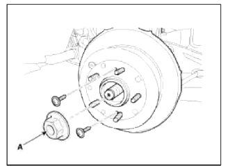
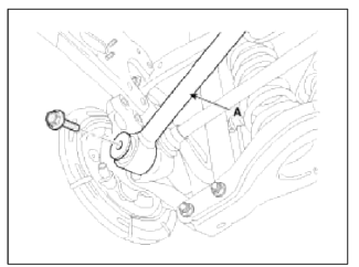
2. Remove the rear wheel and the (A) from rear hub.
Tightening torque: 88.3 ~ 107.8N.m (9.0 ~ 11.0kgf.m, 65.0 ~ 79.5lb-ft)
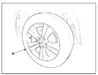
CAUTION
Be careful not to damage to the hub bolts when removing the rear wheel and the (A).
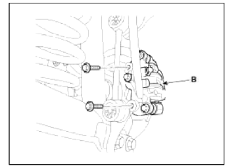
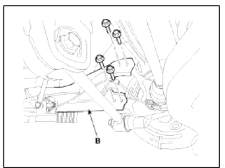
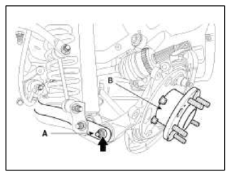
3. Remove the brake caliper mounting bolts, and then hold the brake caliper assembly (B) with wire.
Tightening torque: 78.4 ~ 98.0N.m (8.0 ~ 10.0kgf.m, 57.8 ~ 72.3lb-ft)
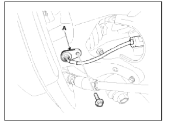
4. Remove the wheel speed sensor (A), from the knuckle.
Tightening torque: 6.8 ~ 10.8N.m (0.7 ~ 1.1kgf.m, 5.1 ~ 7.9lb-ft)
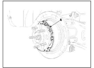
5. Remove castle nut (A) from the rear hub.
Tightening torque: 196.1 ~ 274.5N.m (20.0 ~ 28.0kgf.m, 144.6 ~ 202.5lb-ft)
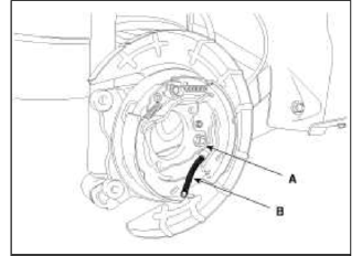
6. Remove the rear brake lining assembly (A). (Refer to BR group - Parking brake system)
7. Remove the parking brake cable (B) from the brake shoe (A).
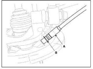
8. Remove the parking brake cable retaining (B), from the parking brake cable (A).
9. Remove the assist arm (A) from the rear axle carrier.
Tightening torque: 137.2 ~ 156.9N.m (14.0 ~ 16.0kgf.m, 101.2 ~ 115.7lb-ft)
10. Remove the trailing arm (B) from the rear axle carrier.
Tightening torque: 34.3 ~ 53.9N.m (3.5 ~ 5.5kgf.m, 25.3 ~ 39.7lb-ft)
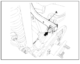
11. Remove the upper arm (A) from the rear axle carrier.
Tightening torque: 98.0 ~ 117.6N.m (10.0 ~ 12.0kgf.m, 72.3 ~ 86.7lb-ft)
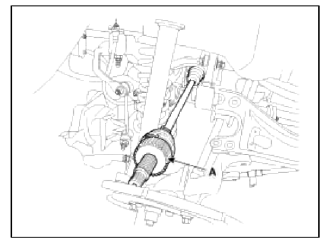
12. Push the rear axle carrier outward and separate the driveshaft (A) from the axle hub.
13. Remove the lower arm (A) from the rear axle carrier (B).
Tightening torque: 137.2 ~ 156.9N.m (14.0 ~ 16.0kgf.m 101.2 ~ 115.7lb-ft)
Inspection
1. Check the hub for cracks and the splines for wear.
2. Check the brake disc for scoring and damage.
3. Check the rear axle carrier for cracks.
4. Check the bearing for cracks or damage.
Disassembly
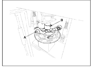
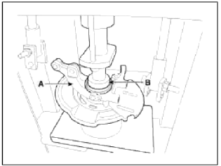
1. Remove the hub assembly form the near knuckle assembly.
- Install the rear knuckle assembly (A) on press.
- Lay a suitable adapter (B) upon the hub assembly shaft.
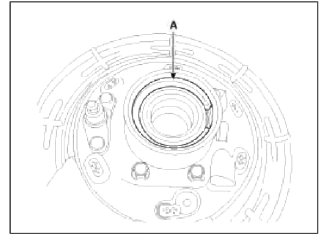
2. Using the snap ring pliers, remove the snap ring (A).
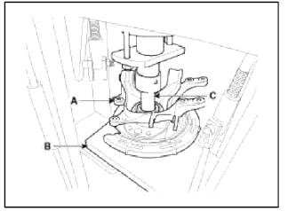
3. Remove the hub bearing outer race form the hub assembly.
- Lay the knuckle assembly (A) upon a suitable adapter (B).
- Lay a suitable adapter (C) upon the hub bearing outer race.
- Remove the hub bearing outer race from the knuckle assembly by using press.
4. Replace hub bearing with a new one.
Reassembly
1. Install the hub bearing to the knuckle assembly.
- Lay the knuckle assembly (A) on press.
- Lay a new hub bearing upon the knuckle assembly (A).
- Lay a suitable adapter (B) upon the hub bearing.
- Install the hub bearing to the knuckle assembly by using press.
CAUTION
Do not press against the inner race of the hub bearing because that can cause damage to the bearing assembly.
Always use a new wheel bearing assembly.
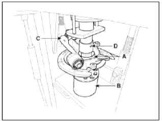
2. Install the hub assembly to the knuckle assembly.
- Lay the hub assembly (A) upon a suitable adapter (B).
- Lay the knuckle assembly (C) upon the hub assembly (A).
- Lay a suitable adapter (D) upon the hub bearing.
- Install the hub assembly (A) to the knuckle assembly (C) by using press.
CAUTION
Do not press against the inner race of hub bearing because that can cause damage to the bearing assembly.
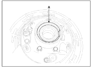
3. Install the snap ring (A).
READ NEXT:
 Components and ComponentsLocation | Repair procedures
Component location
Coupling
Sub frame
Assist arm
Lower arm
Upper arm
Trailing arm
Coil spring
Shock absorber
Stabilizer
Drive shaft
Dif
SEE MORE:
Speakers
Repair procedures
Inspection
1. Troubleshooting for Speaker
Basic inspection of speaker
Inspect the sound from speaker after verifying that the speaker mounting
screws are removed and the wiring
connector is connected to remove any possible vibration transmitted from body
trim
Temperature Control Actuator
Components and
Components Location
Component Location
Description and
Operation
Description
1. Heater unit includes mode control actuator and temperature control
actuator.
2. Temperature control actuator is located at the heater unit. It regulates the
temperature by the pr
Content
- Home
- Kia Sportage - Fifth generation (NQ5) - (2022-2026) - Owner's Manual
- Kia Sportage - Second generation (JEKM) (2005-2015) - Body Workshop Manual
- Kia Sportage Third generation (SL) - (2011-2016) - Service and Repair Manual
- Sitemap
- Top articles
