Kia Sportage: Repair procedures | Components and Components Location | Transaxle Control Module (TCM)
Adjustment
TCM Learning
When shift shock is occurred or parts related with the transaxle are replaced. TCM learning should be performed.
In the following case, TCM learning is required.
- Transaxle assembly replacement
- TCM replacement
- TCM upgrading
1. TCM learning condition
- ATF temperature: 40~100ºC (104-212ºF)
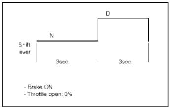
2. TCM learning procedure
- Stop learning
Repeat the below shift pattern four tunes or more with stepping on the brake.
- Driving learning
- Drive the vehicle through all gears at D range. Drive from stop to 1st to 2nd to 3rd to 4th to 5th to 6th with keeping fixed throttle open.
- Down shift from 6th to 5th, 5th to 4th, 4th to 3rd, 3rd to 2nd, 2nd to 1st.
- Repeat the above driving pattern four times or more.
Up-shift throttle open : 15-25%
Schematic Diagrams
Circuit Diagram
Components and Components Location
Components Location
[Vehicle Components]
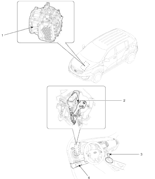
- Automatic transaxle
- Transaxle control module (TCM)
- Shift lever
- (DLC)
[Transaxle Components]
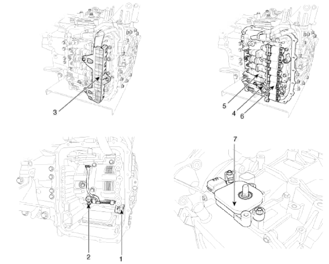
- Input speed sensor
- Output speed sensor
- Solenoid valve connect
- Oil temperature sensor
- Valve body assembly
- Solenoid valve
- Inhibitor switch
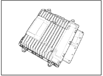
Transaxle Control Module (TCM)
Description and Operation
Description
Transaxle Control Module (TCM) is the automatic transaxle's brain. The module receives and processes signals from various sensors and implements a wide range of transaxle controls to ensure optimal driving conditions for the driver. TCM is programmed for optimal response to any on-road situation. In the event of a transaxle failure or malfunction, TCM stores the fault information in memory so that the technician may reference the code and quickly repair the transaxle.
Functions
- Monitors the vehicle's operating conditions to determine the optimal gear setting.
- Performs a gear change if the current gear setting differs from the identified optimal gear setting.
- Determines the need for damper clutch (D/C) activation and engages the clutch accordingly.
- Calculates the optimal line pressure level by constantly monitoring the torque level and adjusts the pressure accordingly.
- Diagnoses the automatic transaxle for faults and failures.
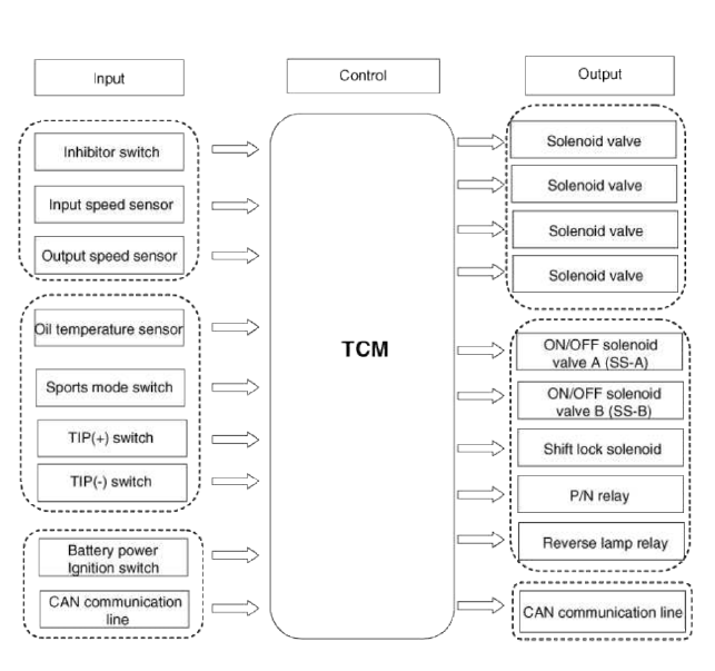
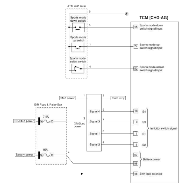
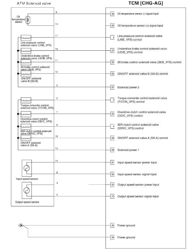
Schematic Diagrams
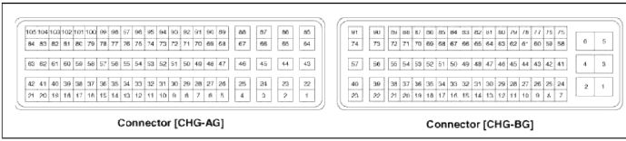
1. TCM Connector and Terminal Function
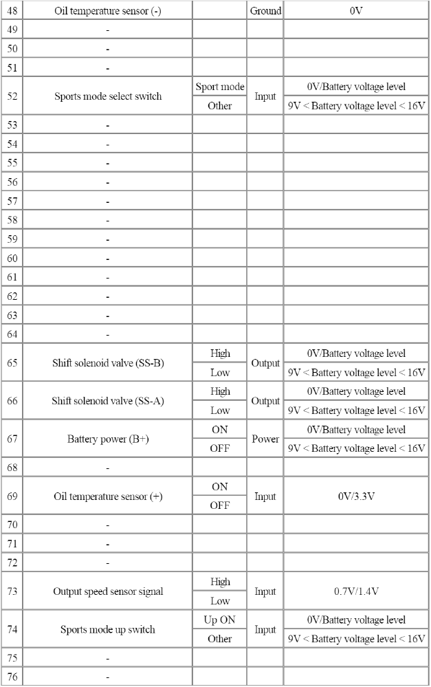
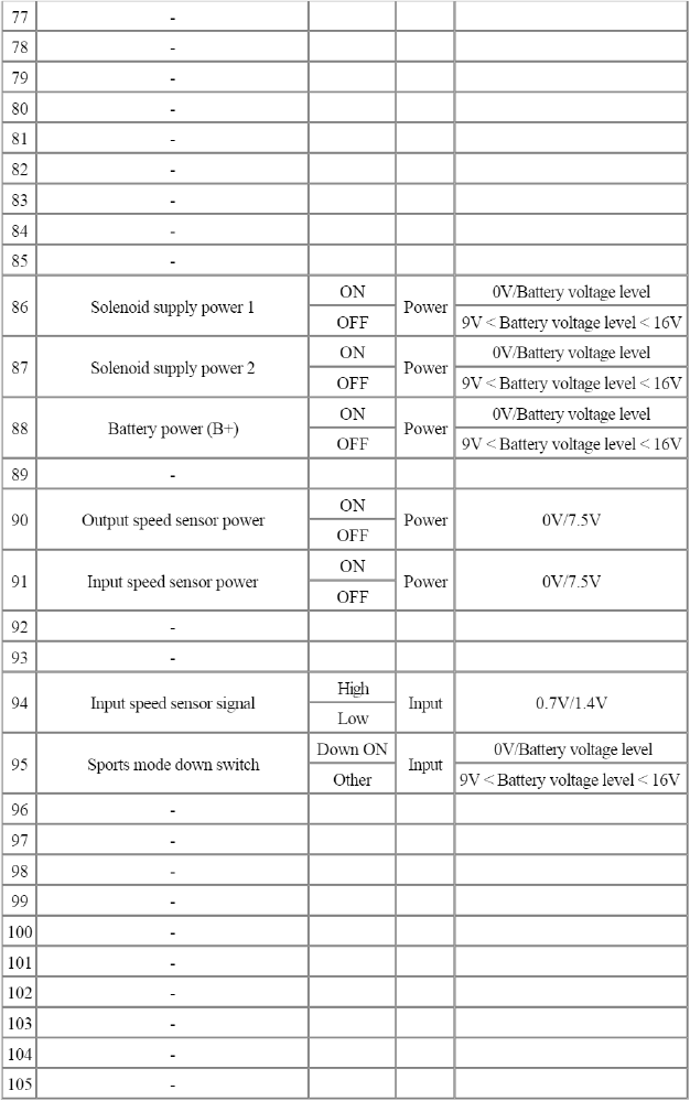
2. TCM Terminal Function
Connector [CHG-AG]
- -
- Line pressure control solenoid valve (LINE_VFS)
- Torque converter control solenoid valve (T/CON_VFS)
- 35R clutch control solenoid valve (35R/C_VFS)
- -
- -
- Inhibitor switch signal "S1"
- Inhibitor switch signal "S2"
- Inhibitor switch signal "S3"
- Inhibitor switch signal "S4"
- -
- -
- -
- -
- -
- -
- -
- -
- -
- -
- -
- -
- Underdrive brake control solenoid valve (UD/B_VFS)
- 26 brake control solenoid valve (26/B_VFS)
- Overdrive clutch control solenoid valve (OD/C_VFS)
- -
- -
- -
- -
- -
- -
- -
- -
- -
- -
- -
- -
- -
- -
- -
- -
- -
- -
- Ground (Power 1)
- Ground (Power 2)
- Shift lock solenoid
- -
- Oil temperature sensor (-)
- -
- -
- -
- Sports mode select switch
- -
- -
- -
- -
- -
- -
- -
- -
- -
- -
- -
- -
- Shift solenoid valve (SS-B)
- Shift solenoid valve (SS-A)
- Battery (B+)
- -
- Oil temperature sensor (+)
- -
- -
- -
- Output speed sensor signal
- Sports mode up switch
- -
- -
- -
- -
- -
- -
- -
- -
- -
- -
- -
- Solenoid supply power 1
- Solenoid supply power 2
- Battery (B+)
- -
- Output speed sensor power
- Input speed sensor power
- -
- -
- Input speed sensor signal
- Sports mode down switch
- -
- -
- -
- -
- -
- -
- -
- -
- -
- -
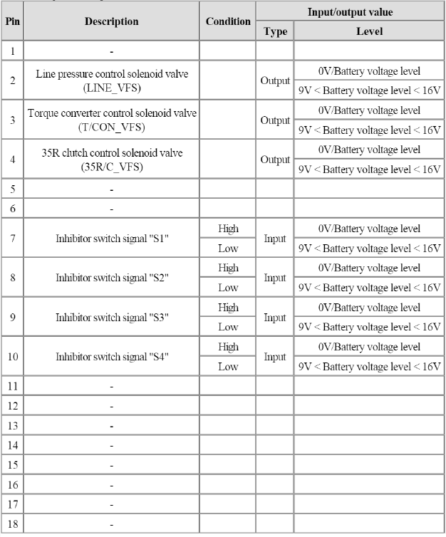
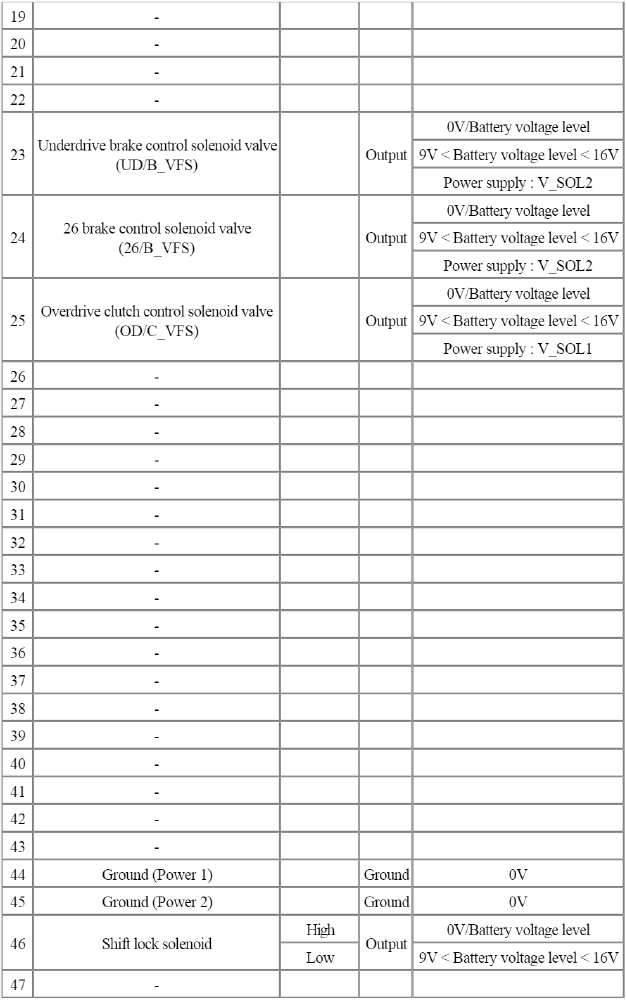
TCM Terminal Input/Output Signal
Connector [CHG-AG]
Circuit Diagram
Repair procedures
Inspection
TCM Problem Inspection Procedure
1. TEST TCM GROUND CIRCUIT: Measure resistance between TCM and chassis ground using the backside of TCM harness connector as TCM side check point. If the problem is found, repair it.
Specification: Below 1Ω
2. TEST TCM CONNECTOR: Disconnect the TCM connector and visually check the ground terminals on TCM side and harness side for bent pins or poor contact pressure. If the problem is found, repair it.
3. If problem is not found in Step 1 and 2, the TCM could be faulty. If so, make sure there were no DTC's before swapping the TCM with a new one, and then check the vehicle again. If DTC's were found, examine this first before swapping TCM.
4. RE-TEST THE ORIGINAL TCM: Install the original TCM (may be broken) into a known-good vehicle and check the vehicle. If the problem occurs again, replace the original TCM with a new one. If problem does not occur, this is intermittent problem (Refer to "Intermittent Problem Inspection Procedure" in Basic Inspection Procedure).
Replacement
1. Turn ignition switch OFF and disconnect the negative (-) battery cable.
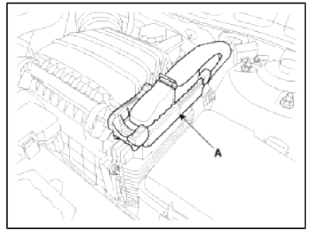
2. Disconnect the TCM Connector (A).
3. Remove the air cleaner assembly.
(Refer to "Intake And Exhaust System" in EM group)
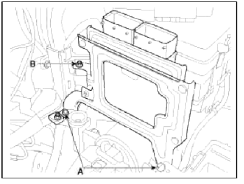
4. Remove the mounting bolts (A) and nut (B), and then remove the TCM assembly (C).
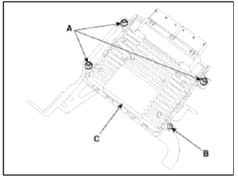
5. Remove the installation nuts (A) and screw (B), and then remove the TCM (C) from the bracket.
Installation
1. Installation is reverse of removal.
NOTE
In the case of the vehicle equipped with immobilizer or button engine start system, perform "Key Teaching" procedure together (Refer to "Immobilizer" or "Button Engine Start System in BE group).
READ NEXT:
 Transaxle Oil Temperature Sensor
Description and Operation
Description
Transaxle oil temperature sensor monitors the automatic transaxle fluid's
temperature and conveys the readings to
TCM. It is an NTC (Negative Therm
SEE MORE:
Mirror | Cowl Top Cover
Repair procedures
Replacement
Outside Rear View Mirror Assembly Replacement
CAUTION
When prying with a flat-tip screwdriver, wrap it with protective tape, and apply protective tape around the related parts, to prevent damage.
Put on gloves to protect your hands.
1. Remove
Forward/Reverse Parking Distance Warning operation
Parking Safety button
Press the Parking Safety ( )
button to
turn on or off Forward/Reverse Parking
Distance Warning.
When Forward/Reverse Parking Distance
Warning is off (button indicator
light off), if you shift the gear to R
(Reverse), Forward/Reverse Parking
Distance Warnin
Content
- Home
- Kia Sportage - Fifth generation (NQ5) - (2022-2026) - Owner's Manual
- Kia Sportage - Second generation (JEKM) (2005-2015) - Body Workshop Manual
- Kia Sportage Third generation (SL) - (2011-2016) - Service and Repair Manual
- Sitemap
- Top articles
