Kia Sportage: Inspection - Repair procedures
Connecting Rod
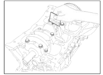
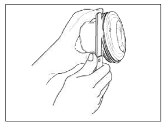
1. Check the connecting rod end play.
Using a feeler gauge, measure the end play while moving the connecting rod back and forth.
End play:
Standard : 0.10 ~ 0.25mm (0.0039 ~ 0.0098in.)
Limit: 0.35mm (0.0138in.)
- If out-of-tolerance, install a new connecting rod.
- If still out-of-tolerance, replace the crankshaft.
2. Check the connecting road bearing oil clearance.
- Check the matchmarks on the connecting rod and cap are aligned to ensure correct reassembly.
- Remove 2 connecting rod cap bolts.
- Remove the connecting rod cap and bearing half.
- Clean the crank pin and bearing.
- Place plastigage across the crank pin.
- Reinstall the bearing half and cap, and torque the bolts.
Tightening torque 17.7~21.6N.m (1.8~2.2kgf.m, 13.0-15.9lb-ft) + 88~92º
NOTE
Do not turn the crankshaft.
- Remove 2 bolts, connecting rod cap and bearing half.
- Measure the plastigage at its widest point.
Standard oil clearance 0.031 ~ 0.045mm (0.00122 ~ 0.00177in.)
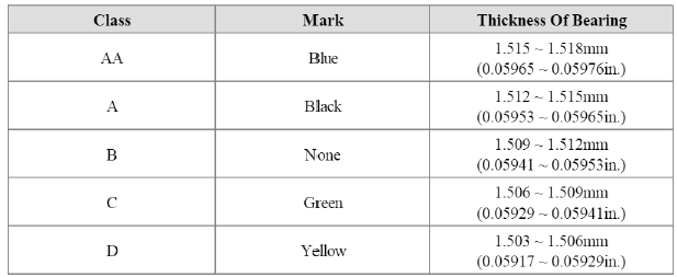
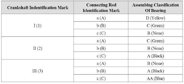
- If the plastigage measures too wide or too narrow, remove the upper half of the bearing, install a new, complete bearing with the same color mark (select the color as shown in the next column), and recheck the clearance.
CAUTION
Do not file, shim, or scrape the bearings or the caps to adjust clearance.
- If the plastigage shows the clearance is still incorrect, try the next larger or smaller bearing (the color listed above or below that one), and check clearance again.
NOTE
If the proper clearance cannot be obtained by using the appropriate larger or smaller bearings, replace the crankshaft and start over.
CAUTION
If the marks are indecipherable because of an accumulation of dirt and dust, do not scrub them with a wire brush or scraper. Clean them only with solvent or detergent.
Connecting Rod Identification Mark
Connecting Rod Specifications
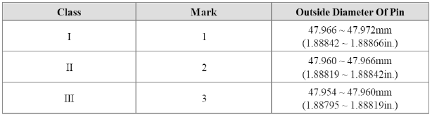
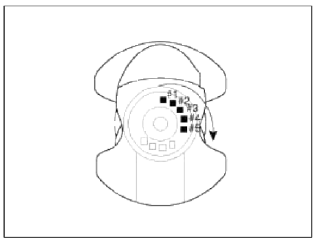
Crankshaft Pin Identification Mark
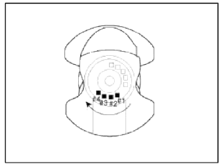
NOTE
Conform to read stamping order as shown arrow direction from #1.
Crankshaft Specifications
Connecting Rod Bearing Identification Mark
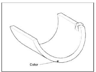
Connecting Rod Bearing Specifications
Selection Chart For Connecting Rod Bearings
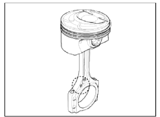
3. Inspect the connecting rods.
- When reinstalling, make sure that cylinder numbers put on the connecting
rod and cap at disassembly match.
When a new connecting rod is installed, make sure that the notches for holding the bearing in place are on the same side.
- Replace the connecting rod if it is damaged on the thrust faces at either end. Also if step wear or a severely rough surface of the inside diameter of the small end is apparent, the rod must be replaced as well.
- Using a connecting rod aligning tool, check the rod for bend and twist. If the measured value is close to the repair' limit, correct the rod by a press. Any connecting rod that has been severely bent or distorted should be replaced.
Allowable bend of connecting rod : 0.05mm (0.0020 in.) or less for 100mm (3.94 in.)
Allowable twist of connecting rod : 0.10mm (0.0039 in.) or less for 100mm (3.94 in.)
Crankshaft
1. Check the crankshaft bearing oil clearance.
- To check main bearing-to-journal oil clearance, remove the main caps and bearing halves.
- Clean each main journal and bearing half with a clean shop tower.
- Place one strip of plastigage across each main journal.
- Reinstall the bearings and caps, then torque the bolts.
Tightening torque : 14.7N.m (1.5kgf.m, 10.8lb-ft) + 27.5~31.4N.m (2.8~3.2kgf.m, 20.3~23.1lb-ft) + 120~125º
NOTE
Do not turn the crankshaft.
- Remove the cap and bearing again, and measure the widest part of the plastigage.
Standard oil clearance 0.020 ~ 0.038mm (0.00079 ~ 0.00150in.)
- If the plastigage measures too wide or too narrow, remove the upper half of the bearing, install a new, complete bearing with the same color mark (select the color as shown in the next column), and recheck the clearance.
CAUTION
Do not file, shim, or scrape the bearings or the caps to adjust clearance.
- If the plastigage shows the clearance is still incorrect, try the next larger or smaller bearing (the color listed above or below that one), and check clearance again.
NOTE
If the proper clearance cannot be obtained by using the appropriate larger or smaller bearings, replace the crankshaft and start over.
CAUTION
If the marks are indecipherable because of an accumulation of dirt and dust, do not scrub them with a wire brush or scraper. Clean them only with solvent or detergent.
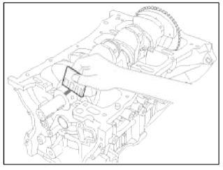
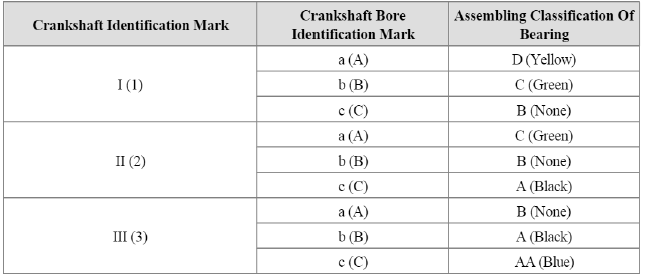
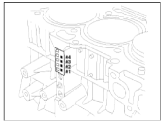
Crankshaft Bore Identification Mark
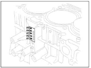
Letters have been stamped on the block as a mark for the size of each of the 5 main journal bores.
Use them, and the numbers or bar stamped on the crank (marks for main journal size), to choose the correct bearings.
Cylinder Block Specifications
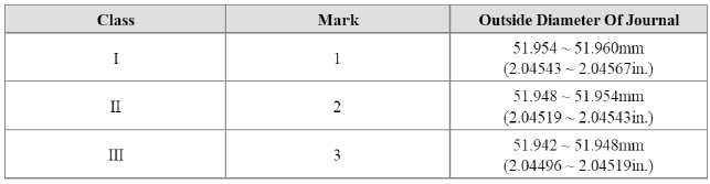
Crankshaft Journal Identification Mark
NOTE
Conform to read stamping order as shown arrow direction from #1.
Crankshaft Specifications
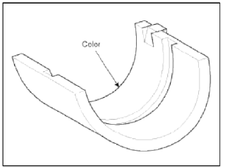
Crankshaft Bearing Identification Mark
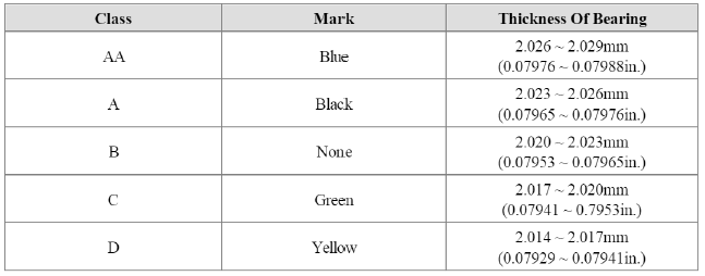
Crankshaft Bearing Specifications
Selection Chart For Crankshaft Bearings
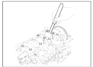
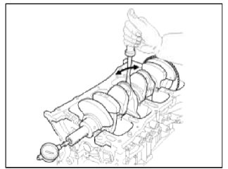
2. Check crankshaft end play.
Using a dial indicator, measure the thrust clearance while prying the crankshaft back and forth with a screwdriver.
End play
Standard: 0.07 ~ 0.25mm (0.0028 ~ 0.0098in.)
Limit: 0.30mm (0.0118in.)
If the end play is greater than maximum, replace the thrust bearings as a set.
Thrust bearing thickness: 1.925 ~ 1.965mm (0.07579 ~ 0.07736in.)
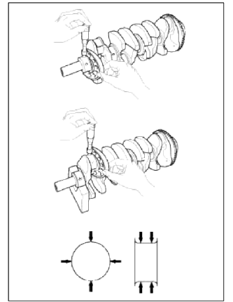
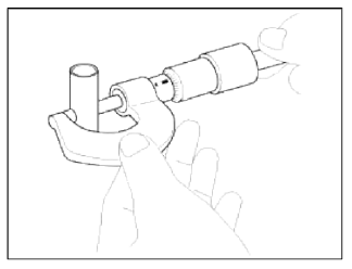
3. Inspect main journals and crank pins.
Using a micrometer, measure the diameter of each main journal and crank pin.
Main journal diameter: 51.942 ~ 51.960mm (2.04496 ~ 2.04567in.)
Crank pin diameter: 47.954 ~ 47.972mm (1.88795 ~ 1.88866in.)
Cylinder Block
1. Remove gasket material.
Using a gasket scraper, remove all the gasket material from the top surface of the cylinder block.
2. Clean cylinder block.
Using a soft brush and solvent, thoroughly clean the cylinder block.
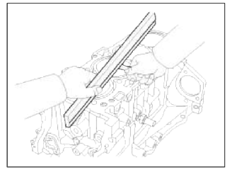
3. Inspect top surface of cylinder block for flatness.
Using a precision straight edge and feeler gauge, measure the surface contacting the cylinder head gasket for warpage.
Flatness of cylinder block gasket surface
Standard: Less than 0.05mm (0.0019in.) for all Less than 0.02 (0.0007in.) for 100mm (3.9370in.) x 100mm (3.9370in.)
4. Inspect cylinder bore diameter.
Visually check the cylinder for vertical scratchs.
If deep scratches are present, replace the cylinder block.
5. Inspect cylinder bore diameter.
Using a cylinder bore gauge, measure the cylinder bore diameter at position in the thrust and axial directions.
Standard diameter 86.00 ~ 86.03mm (3.3858 ~ 3.3870in.)

NOTE
Measurement position points (from the bottom of the cylinder block): 110.7mm(4.3582in.)/160mm(6.2992in.)/210mm(8.2677in.)
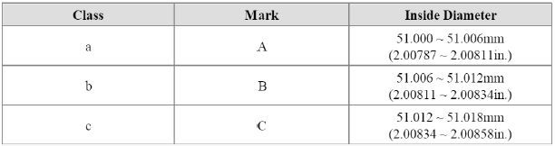
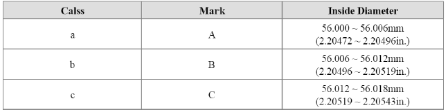
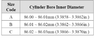
6. Check the cylinder bore size code on the cylinder block.
Cylinder Bore Inner Diameter
7. Check the piston size code on the piston top face.
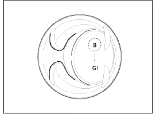
NOTE
Stamp the grade mark of basic diameter with rubber stamp.
Piston Outer Diameter
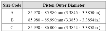
8. Select the piston related to cylinder bore class.
Clearance : 0.020 ~ 0.040mm (0.00079 ~ 0.00157in.)
Piston And Rings
1. Clean piston
- Using a gasket scraper, remove the carbon from the piston top.
- Using a groove cleaning tool or broken ring, clean the piston ring grooves.
- Using solvent and a brush, thoroughly clean the piston.
NOTE
Do not use a wire brush.
2. The standard measurement of the piston outside diameter is taken 17mm (0.67in.) from the top land of the piston.
Standard diameter 85.970 ~ 86.000mm (3.3846 ~ 3.3858in.)

3. Calculate the difference between the cylinder bore diameter and the piston diameter.
Piston-to-cylinder clearance 0.020 ~ 0.040mm (0.00079 ~ 0.00157in.)
4. Inspect the piston ring side clearance.
Using a feeler gauge, measure the clearance between new piston ring and the wall of the ring groove.
Piston ring side clearance
Standard
No.1 : 0.050 ~ 0.080mm (0.00197 ~ 0.00315m.)
No.2 : 0.040 ~ 0.080mm (0.00157 ~ 0.00315m.)
Oil ring : 0.020 ~ 0.055mm (0.00079 ~ 0.00217m.)
Limit
No.1 : 0.100mm(0.00394in.)
No.2 : 0.100mm (0.00394in.)
Oil ring : 0.100mm (0.00394in.)
If the clearance is greater than maximum, replace the piston.
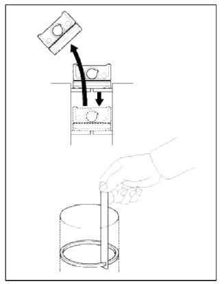
5. Inspect piston ring end gap.
To measure the piston ring end gap, insert a piston ring into the cylinder bore. Position the ring at right angles to the cylinder wall by gently pressing it down with a piston. Measure the gap with a feeler gauge. If the gap exceeds the service limit, replace the piston ring. If the gap is too large, recheck the cylinder bore diameter against the wear limits. If the bore is over the service limit, the cylinder block must be replaced.
Piston ring end gap
Standard
No.1 : 0.15 ~ 0.30mm (0.0059 ~ 0.0118in.)
No.2 : 0.37 ~ 0.52mm (0.0145 ~ 0.0204in.)
Oil ring : 0.20 ~ 0.50mm (0.0079 ~ 0.0197in.)
Limit
No.1 : 0.60mm (0.0236in.)
No.2 : 0.70mm (0.0275in.)
Oil ring : 0.80mm (0.0315in.)
Piston Pins
1. Measure the diameter of the piston pin.
Piston pin diameter
21.997 ~ 22.000mm (0.86602 ~ 0.86614in.)
2. Measure the piston pin-to-piston clearance.
Piston pin-to-piston clearance 0.003 ~ 0.010mm (0.00012 ~ 0.00039in.)
3. Check the difference between the piston pin diameter and the connecting rod small end diameter.
3. Check the difference between the piston pin diameter and the connecting rod small end diameter.
Piston pin-to-connecting rod interference 0.005 ~ 0.014mm (0.00020 ~ 0.00055in.)
READ NEXT:
 Reassembly - Repair procedures
NOTE
Thoroughly clean all parts to assembled.
Before installing the parts, apply fresh engine oil to all sliding
and rotating surfaces.
Replace all gaskets, O-rings and oil seals with new p
Coolant
Repair procedures
Refilling And Bleeding
WARNING
Never remove the radiator cap when the engine is hot. Serious scalding
could be caused by hot fluid under high
pressure escaping from the radiato
SEE MORE:
Engine Control Module (ECM)
Schematic Diagrams
ECM Terminal And Input/Output signal
ECM Terminal Function
Connector [CHTG-AG]
Connector [CHTG-BG]
ECM Terminal Input/Output signal
Connector [CHTG-AG]
Connector [CHTG-BG]
Circuit Diagram
Repair procedures
Removal
CA
Active air flap
Active air flap system controls the air
flap below the front bumper to cool the
vehicle parts and improve energy efficiency.
Active air flap malfunction
Check Active Air Flap System
The active air flap system may not operate
normally if the air flap is temporarily
opened due to fo
Content
- Home
- Kia Sportage - Fifth generation (NQ5) - (2022-2026) - Owner's Manual
- Kia Sportage - Second generation (JEKM) (2005-2015) - Body Workshop Manual
- Kia Sportage Third generation (SL) - (2011-2016) - Service and Repair Manual
- Sitemap
- Top articles
