Kia Sportage: Specifications, Components and Components Location | Repair procedures
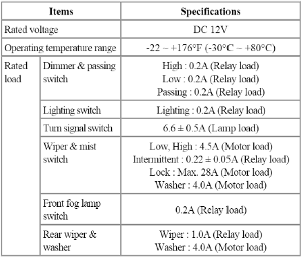
Specifications
Specifications
Components and Components Location
Component (1)

<Installation order: A→B→C→D>
- Steering column shaft
- Lighting switch
- Wiper and washer switch
- Screw
- Clock spring
Component (2)
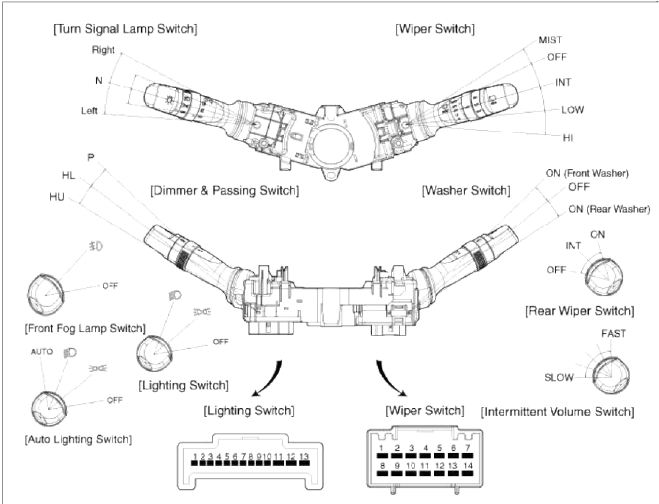
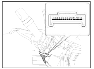
Lighting (13 pin)
- Tail lamp switch
- Lighting switch GND
- Auto light switch
- Head lamp switch
- Fog lamp switch base
- Front fog lamp switch
- -
- Head lamp low
- Head lamp high
- Dimmer switch base
- Turn signal left
- Turn signal base
- Turn signal right
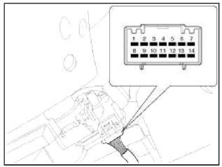
Wiper & Washer (14 pin)
- Mist switch
- Wiper parking
- Wiper low speed
- Intermittent volume base
- Intermittent time base
- Rear wiper switch
- Intermittent rear wiper switch
- Intermittent wiper switch
- Wiper high speed
- IGN2 (front washer & wiper)
- Front washer switch
- IGN2 (rear wiper & washer)
- Rear washer switch
- -
Repair procedures
Removal
1. Disconnect the negative (-) battery terminal.
2. Remove the steering column upper and lower shrouds (A) after removing 3 screws.
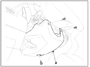
NOTE
Take care not to damage and scratch the shrouds and its related parts.
Take care not to damage the hook when removing the upper and lower shrouds.
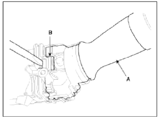
3. Disconnect the light switch connector (A) and the wiper switch connector (B).
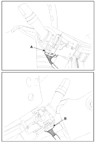
4. Remove the wiper switch (A) by pushing the lock pin (B).
NOTE
When removing the wiper & washer switch only, release the lock of wiper switch without removing the steering wheel.
5. Remove the steering wheel.
(Refer to the ST group - "Steering column and shaft")
6. Remove the clock spring.
(Refer to the RT group - "Airbag module")
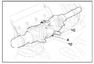
7. Loosen the 2 screws from the multifunction switch assembly (A).
Installation
1. Install the multifunction switch.
2. Install the clock spring and steering wheel.
3. Install the steering column upper and lower shrouds.
4. Install the steering wheel.
Inspection
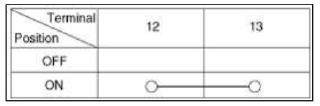
Lighting Switch Inspection
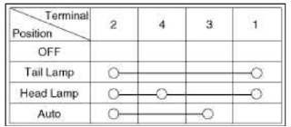
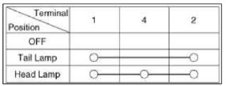
1. With the multi function switch in each position, make sure that continuity exists between the terminals below.
If continuity is not as specified, replace the multi-function switch.
Lighting switch (Auto Light)
Lighting Switch
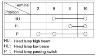
Dimmer And Passing Switch
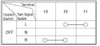
Turn Signal Switch
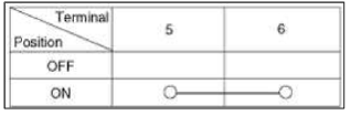
Front Fog Lamp
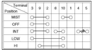
Wiper And Washer Switch Inspection
1. With the multi function switch in each position, make sure that continuity exists between the terminals below.
If continuity is not as specified, replace the multi-function switch.
Wiper Switch
Washer Switch
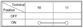
Rear Wiper Switch
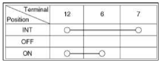
Rear Washer Switch
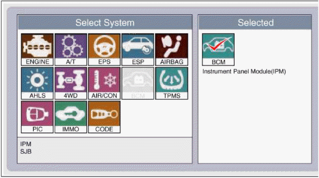
Inspection (With GDS)
1. Check BCM input/output specification of multifunction switch using the GDS. If the specification is abnormal, replace the lamp or wiper switch.
2. If diagnosis is required on the multifunction switch select model and "BCM".
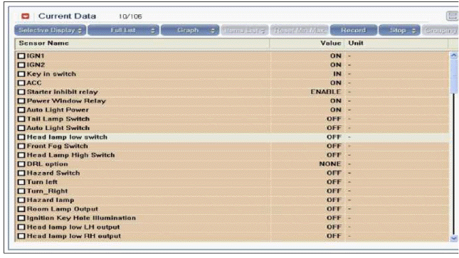
3. Select "Current data" and check the input/output condition of "Multifunction switch".
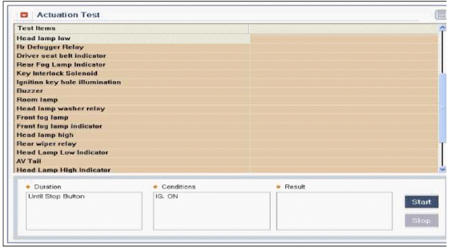
4. To perform test on "Multifunction switch" outputs, select "Actuation test".
READ NEXT:
 Horn
Horn
Components and Components Location
Component Location
Horn switch
Horn relay (Engine room
compartment)
Horn (Low pitch)
Clock spring
Repair procedures
Removal
1. Remove the r
SEE MORE:
Trip information (trip computer)
Drive info
Accumulated trip distance
Average fuel efficiency
Total driving time
The trip computer mode displays information
related to vehicle driving parameters
including fuel economy, tripmeter
information and timer.
* For more details, refer to "Trip information
(tri
Disassembling spot welded area
Most body parts are spot welded. In order to disassemble the damaged area, it
is best to disassemble the spot
welded area from the body frame using a spot cutter or candle type edge drill
bit. Do not use a drill bit with a tapered
edge. Center punch middle of spot weld to insure the entire spo
Content
- Home
- Kia Sportage - Fifth generation (NQ5) - (2022-2026) - Owner's Manual
- Kia Sportage - Second generation (JEKM) (2005-2015) - Body Workshop Manual
- Kia Sportage Third generation (SL) - (2011-2016) - Service and Repair Manual
- Sitemap
- Top articles
