Kia Sportage: Schematic Diagrams, Description and Operation
Schematic Diagrams
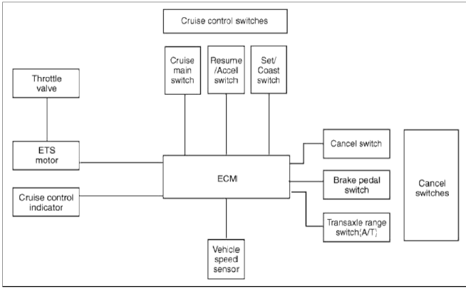
System Block Diagram
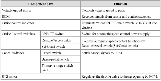
Component Parts And Function Outline
* ETS : Electronic Throttle System
Description and Operation
Cruise Control
The cruise control system is engaged by the cruise "ON/OFF" main switch located on right of steering wheel column. The system has the capability to cruise, coast, accelerate and resume speed.
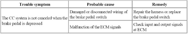
It also has a safety interrupt, engaged upon depressing brake or shifting select lever.
The ECM is the control module for this system. The main components of cruise control system are mode control switches, transmission range switch, brake switch, vehicle speed sensor, ECM and ETS motor that connect throttle body.
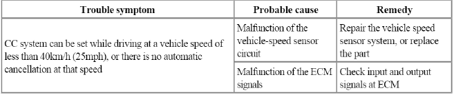
The ECM contains a low speed limit which will prevent system engagement below a minimum speed of 40km/h (25mph).
The operation of the controller is controlled by mode control switches located on steering wheel.
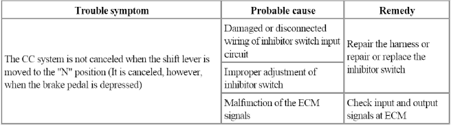
Transmission range switch and brake switch are provided to disengage the cruise control system. The switches are on brake pedal bracket and transmission. When the brake pedal is depressed or select lever shifted, the cruise control system is electrically disengaged and the throttle is returned to the idle position.
Cruise main switch (ON/OFF)
The cruise control system is engaged by pressing the cruise "ON/OFF" main switch. Pressing the cruise "ON/OFF" main switch again releases throttle, clears cruise memory speed, and puts vehicle in a non-cruise mode.
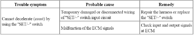
Set/Coast switch (SET/-)
The "SET/-" switch located on right of steering wheel column has two functions.
The set function - Push the "SET/-" switch and release it at the desired speed. The SET indicator light in the instrument cluster will illuminate. Release the accelerator pedal. The desired speed will automatically be maintained.
The coast function - Push the "SET/-" switch and hold it when the cruise control is on. The vehicle will gradually slow down. Release the switch at the desired speed. The desired speed will be maintained.
Push the "SET/-" switch and release it quickly. The cruising speed will decrease by 1.6km/h (1.0mph).
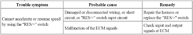
Resume/Accel switch (RES/+)
The "RES/+" switch located on right of steering wheel column has two functions.
The resume function - If any method other than the cruise "ON/OFF" main switch was used to cancel cruising speed temporarily and the system is still activated, the most recent set speed will automatically resume when the "RES/+" switch is pushed. It will not resume, however, if the vehicle speed has dropped below approximately 40km/h (25mph).
The accel function - Push the "RES/+" switch and hold it when the cruise control is on. The vehicle will gradually accelerate. Release the switch at the desired speed. The desired speed will be maintained.
Push the "RES/+" switch and release it quickly. The cruising speed will increase by 1.6km/h (1.0mph).
Cancel switch (CANCEL)
The cruise control system is temporarily disengaged by pushing the "CANCEL" switch.
Cruise speed canceled by this switch can be recovered by pushing the "RES/+" switch.
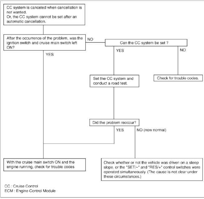
Troubleshooting
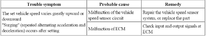
Trouble Symptom Charts
Trouble Symptom 1
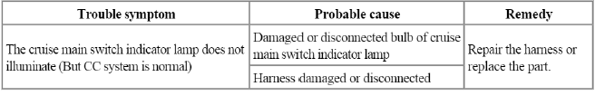
Trouble Symptom 2
Trouble Symptom 3
Trouble Symptom 4
Trouble Symptom 5
Trouble Symptom 6
Trouble Symptom 7
Trouble Symptom 8
READ NEXT:
 Cruise Control Switch
Schematic Diagrams
Circuit Diagram
[Auto Cruise Control]
Connector RH
ILL (-)
ILL (+)
-
-
-
ACC GND
ACC signal
ACC power
Repair procedures
Removal and Installation
General Information
Specifications
Specifications
Tightening Torques
Repair procedures
Compression Pressure Inspection
NOTE
If the there is lack of power, excessive oil consumption or poor
SEE MORE:
Climate Seat
Components and Components Location
Components
[Front Seat]
Ventilation blower
Ventilation ECU
Ventilation seat switch
Blower connector
Heater connector
Ventilation ECU
connector
Schematic Diagrams
Schematic Diagram
[Front Seat]
Connector Configurations
Bl
General Information
Specifications
Specifications
Front Suspension
Rear Suspension
Wheel & Tire
Wheel Alignment
Tightening torque
Front Suspension
Rear Suspension
Special Service Tools
Special Service Tools
Troubleshooting
Troubleshooting
Wheel/tire noise, vibration
Content
- Home
- Kia Sportage - Fifth generation (NQ5) - (2022-2026) - Owner's Manual
- Kia Sportage - Second generation (JEKM) (2005-2015) - Body Workshop Manual
- Kia Sportage Third generation (SL) - (2011-2016) - Service and Repair Manual
- Sitemap
- Top articles
