Kia Sportage: Steering Gear box
Components and Components Location
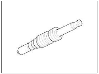
Components
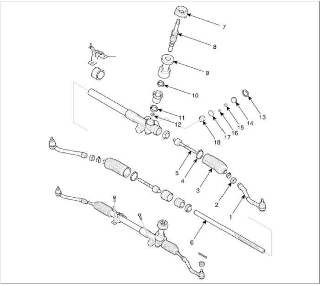
- Tie rod end
- Locknut
- Bellows
- Bellows band
- Tie rod
- Rack bar
- Dust packing
- Pinion assembly
- Dust cap
- Oil seal
- Ball bearing
- Needle bearing
- Lock nut
- Yoke plug
- Yoke spring
- O-ring
- Spring
- Support yoke assembly
Repair procedures
Replacement
1. Remove the front wheel & tire.
Tightening torque: 88.3 ~ 107.9N.m (9.0 ~ 11.0kgf.m, 65.1 ~ 79.6lb-ft)
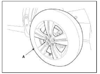
CAUTION
Be careful not to damage to the hub bolts when removing the front wheel & tire (A).
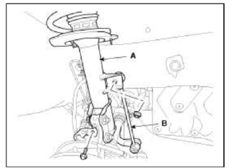
2. Disconnect the stabilizer link (B) with the front stint assembly (A) after loosening the nut.
Tightening torque: 98.1 ~ 117.7N.m (10.0 ~ 12.0kgf.m, 72.3 ~ 86.8lb-ft)
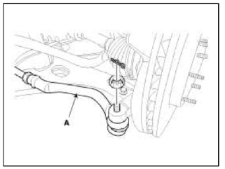
3. Remove the split pin and castle nut and then disconnect the tie-rod end (A) from the front knuckle.
Tightening torque: 23.5 ~ 33.3N.m(2.4 ~ 3.4kgf.m, 17.4 ~ 24.6lb-ft)
4. Loosen the bolt & nut and then remove the lower arm (A).
Tightening torque: 98.1 ~ 117.7N.m (10.0 ~ 12.0kgf.m, 72.3 ~ 86.8lb-ft)
5. Remove the dust cover.
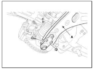
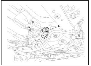
6. Loosen the bolt (A) and then disconnect the universal joint assembly from the pinion of the steering gear box.
Tightening torque: 32.4 ~ 37.3N.m (3.3 ~ 3.8kgf.m, 23.9 ~ 27.5lb-ft)
CAUTION
- Keep the neutral-range to prevent the damage of the clock spring inner cable when you handle the steering wheel.
- Do not use the bolt again.
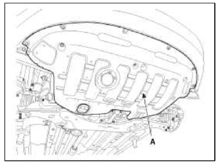
7. Remove the under cover (A).
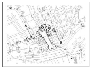
8. Loosen the bolt (A) & nut (B) and then remove the roll rod stopper.
Tightening torque: 107.9 ~ 127.5N.m (11.0 ~ 13.0kgf.m, 79.6 ~ 94.0lb-ft)
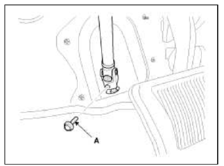
9. Disconnect the muffler rubber hanger (A).
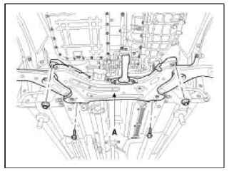
10. Loosen the bolts & nuts and then remove the sub frame.
Tightening torque: 176.5 ~ 196.1N.m (18.0 ~ 20.0kgf.m, 130.2 ~ 144.7lb-ft)
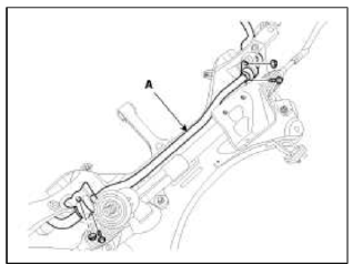
11. Loosen the bolt and then remove the stabilizer (A).
Tightening torque: 44.1 ~ 53.9N.m (4.5 ~ 5.5kgf.m, 32.5 ~ 39.8lb-ft)
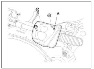
12. Loosen the bolt & nut and then remove the protector (A).
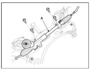
13. Loosen the bolt and then remove the steering gear box (A).
Tightening torque: 58.8 ~ 78.5N.m (6.0 ~ 8.0kgf.m, 43.4 ~ 57.9lb-ft)
14. Installation is the reverse of the removal.
Disassembly
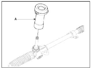
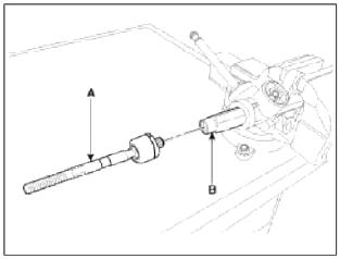
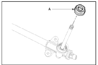
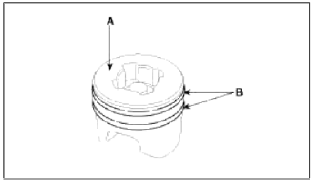
1. Remove the dust packing & cap (A) from the pinion housing.
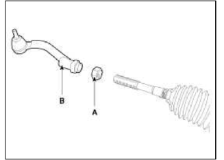
2. Loosen the lock nut and then remove the tie rod end (B) and lock nut (A) from the tie rod.
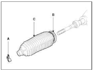
3. Remove the bellows clip (A) and band (B) and then pull the bellows (C) away from the end of the tie rod.
4. Remove the tie rod (B) from the rack bar (A) by unscrewing the tie rod inner ball joint.
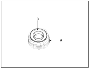
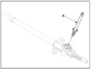
5. Remove the plug (A) from the pinion housing.
6. Remove the oil seal (B) from the plug (A).
7. Remove the yoke plug (A) and spring (B) and then pull out the support yoke (C).
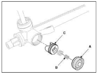
8. Remove the O-ring (B) from the support yoke assembly (A).
9. Pull the pinion assembly (A) out of the pinion housing.
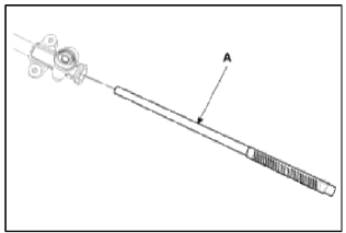
10. Pull the rack bar (A) out of the rack housing.
11. Reassembly is the reverse of the disassembly.
Inspection
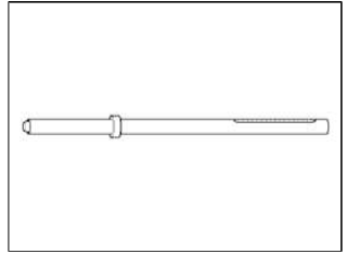
1. Rack bar
- Check the rack gear for damage.
- Check the rack bar for bend and deformation.
2. Pinion assembly
- Check the pinion gear for damage
- Check the oil seal for damage
3. Check the inside of rack housing for damage.
4. Check the bellows for being torn.
READ NEXT:
 General Information
Specifications
Specifications
Front Suspension
Rear Suspension
Wheel & Tire
Wheel Alignment
Tightening torque
Front Suspension
Rear Suspension
Special Service Tools
&nb
SEE MORE:
With the smart key
Door locks
Know how to use the door lock so that
you can lock or unlock the door if necessary.
With the smart key
Carrying the smart key, you may
lock
and unlock the vehicle doors (and liftgate).
Also, you may start the engine.
Refer to the following for more details.
Locking
Pressing
General Information
Specifications
Specifications
Tightening Torques
Special Service Tools
Special Service Tools
Content
- Home
- Kia Sportage - Fifth generation (NQ5) - (2022-2026) - Owner's Manual
- Kia Sportage - Second generation (JEKM) (2005-2015) - Body Workshop Manual
- Kia Sportage Third generation (SL) - (2011-2016) - Service and Repair Manual
- Sitemap
- Top articles
