Kia Sportage: Temperature Control Actuator
Components and Components Location
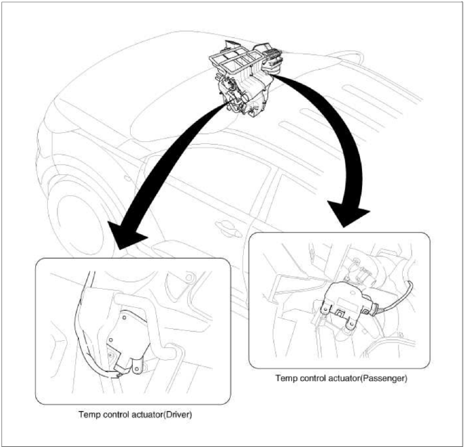
Component Location
Description and Operation
Description
1. Heater unit includes mode control actuator and temperature control actuator.
2. Temperature control actuator is located at the heater unit. It regulates the temperature by the procedure as follows. Signal from control unit adjusts position of temperature door by operating temperature switch and then temperature will be regulated by the hot/cold air ratio decided by position of temperature door.
Repair procedures
Inspection
1. Ignition "OFF".
2. Disconnect the connector of temperature control actuator.
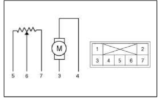
3. Verify that the temperature control actuator operates to the hot position when connecting 12V to the terminal 3 and grounding terminal 4.
Verify that the temperature control actuator operates to the cool position when connecting in the reverse.
[Drive]
- -
- -
- Hot position
- Cool position
- Sensor ground
- Feedback signal
- 5V (Vcc)
4. Check the voltage between terminals 5 and 6 (Drive).
Specification
![[Passenger]](images/books/1921/23/index%20128.png)
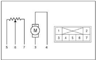
[Passenger]
- -
- -
- Cool position
- Hot position
- 5V (Vcc)
- Feedback signal
- Sensor ground
5. Check the voltage between terminals 6 and 7 (Passenger).
Specification
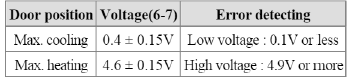
It will feedback current position of actuator to controls.
6. If the measured voltage is not specification, substitute with a known-good temperature control actuator and check for proper operation.
7. If the problem is collected, replace the temperature control actuator.
Replacement
1. Disconnect the negative (-) battery terminal.
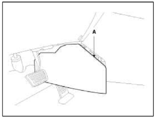
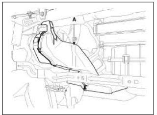
2. Remove the left extension cover (A).
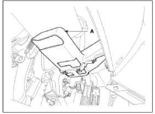
3. Remove the left shower duct (A).
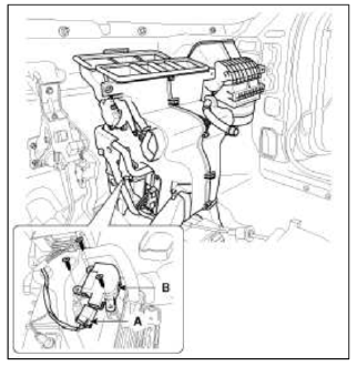
4. Disconnect the temperature control actuator connector (A).
5. Loosen the mounting screw and then remove the temperature control actuator (B).
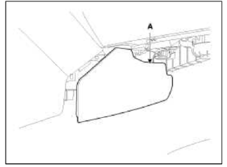
6. Remove the right extension cover (A).
7. Remove the main crash pad.
(Refer to BD group - "Crash Pad")
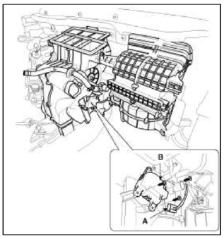
8. Remove the right shower duct (A).
9. Disconnect the temperature control actuator connector (A).
10. Loosen the mounting screw and then remove the temperature control actuator (B).
11. Installation is the reverse order of removal.
READ NEXT:
 Mode Control Actuator
Components and
Components Location
Component Location
Description and Operation
Description
The mode control actuator is located at the heater unit.
It adjusts position of mode d
Blower Unit | Blower Motor
Components and Components Location
Component Location
Components
Intake case (LH)
Intake case (RH)
Blower motor
Intake door
Intake actuator
Mofet [Aut
SEE MORE:
Manual Speed Limit Assist (MSLA)
Speed Limit indicator
Set speed
You can set the speed limit when you do
not want to drive over a specific speed.
If you drive over the preset speed limit,
the warning function operates (set
speed limit will blink, and chime will
sound) until the vehicle speed returns
within the s
Seat belts - Front passenger and rear seat 3-point system with combination locking retractor
The following explains how to fasten the
passenger's and rear seat belts.
Fastening your seat belt:
Combination retractor type seat belts
are installed in the rear seat positions to
help accommodate the installation of
Child Restraint System. Although a combination
retractor is also insta
Content
- Home
- Kia Sportage - Fifth generation (NQ5) - (2022-2026) - Owner's Manual
- Kia Sportage - Second generation (JEKM) (2005-2015) - Body Workshop Manual
- Kia Sportage Third generation (SL) - (2011-2016) - Service and Repair Manual
- Sitemap
- Top articles
