Kia Sportage: Components and Components Location | Steering Column and Shaft
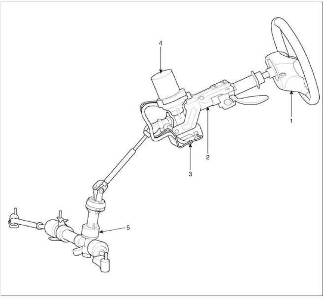
Components
-
Steering wheel
-
Steering column
-
ECU
-
Motor
-
Steering gear box
MDPS Circuit Diagram
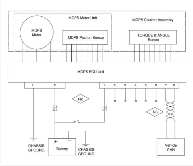
Harness Connector
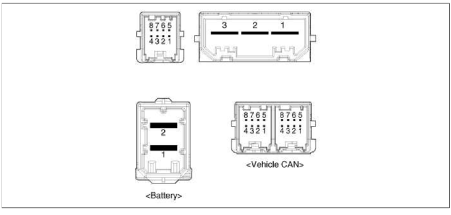
Battery
- Battery -
- Battery +
Vehicle
- IGN
- -
- -
- -
- -
- -
- High_CAN
- Low_CAN
Steering Column and Shaft
Repair procedures
Replacement
1. Disconnect the battery negative cable from the battery and then wait for at least 30 seconds.
2. Turn the steering wheel so that the front wheels can face straight ahead.
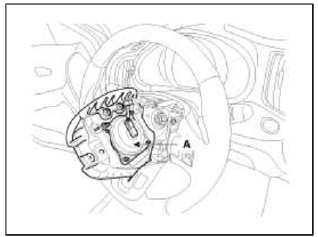
3. Remove the airbag module (A).
(Refer to "Airbag Module" in RT group)
4. Disconnect the locknut (A) & washer (B) and then remove the steering wheel from the steering column shaft.
Tightening torque: 39.2 ~ 49.0N.m (4.0 ~ 5.0kgf.m, 28.9 ~ 36.2lb-ft)
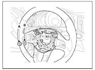
CAUTION
Do not hammer on the steering wheel to remove it may damage the steering column.
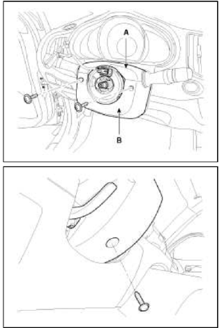
5. Remove the steering column upper (A) and lower (B) shroud.
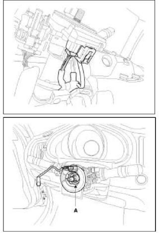
6. Remove the clock spring (A).
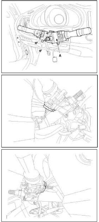
7. Remove the multifunction switches (A).
8. Remove the crash lower panel (A).
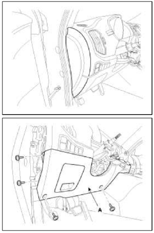
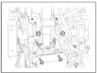
9. Loosen the bolt & nut and then remove the panel (A).
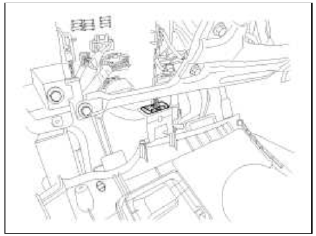
10. Remove the dust cover.
11. Loosen the bolt (A) and then disconnect the universal joint assembly from the pinion of the steering gear box
Tightening torque: 32.4 ~ 37.3N.m (3.3 ~ 3.8kgf.m, 23.9 ~ 27.5lb-ft)
CAUTION
- Do not use the bolt again.
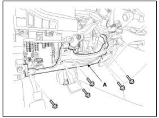
12. Disconnect all connectors connected the steering column.
13. Remove the steering column by loosening the mounting bolts and nuts.
Tightening torque: 12.7 ~ 17.7N.m (1.3 ~ 1.8kgf.m, 9.4 ~ 13.0lb-ft)
14. Installation is the reverse of the removal.
Disassembly
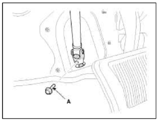
Universal joint assembly
1. Loosen the bolt (A) and then disconnect the universal joint assembly from the steering column assembly.
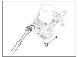
2. Reassembly is the reverse of the disassembly.
Inspection
1. Check the steering column for damage and deformation.
2. Check the join bearing for damage and wear.
3. Check the tilt bracket for damage and cracks.
4. Check the key lock assembly for proper operation and replace it if necessary.
READ NEXT:
 Steering Gear box
Components and Components
Location
Components
Tie rod end
Locknut
Bellows
Bellows band
Tie rod
Rack bar
Dust packing
Pinion assembly
Dust cap
Oil seal
Ball bearing
SEE MORE:
Jack and tools
If you have a flat tire, you can change
the flat tire to a spare tire using tools.
WARNING
Driving on a flat tire will cause permanent
damage to the tire. Re-inflating a
tire after it has been driven on while
severely underinflated or flat may cause
a blowout and a serious crash. Never
attem
Direct Electro Hydraulic Actuator Coupling
Description and Operation
Description
4WD ECU processes signals from various sensors and determines the current
road and driving conditions. The ECU then
utilizes this information to implement precision control over the 4WD coupling's
multi-plate clutch and variably adjust the
amou
Content
- Home
- Kia Sportage - Fifth generation (NQ5) - (2022-2026) - Owner's Manual
- Kia Sportage - Second generation (JEKM) (2005-2015) - Body Workshop Manual
- Kia Sportage Third generation (SL) - (2011-2016) - Service and Repair Manual
- Sitemap
- Top articles
