Kia Sportage: Components and ComponentsLocation | Repair procedures
Components
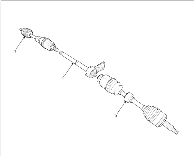
- Front driveshaft (LH)
- Inner shaft
- Front driveshaft (RH)
[LH]
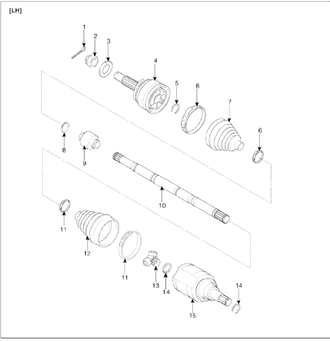
- Split pin
- Castle nut
- Washer
- BJ assembly
- Clip A
- Ð’J boot band
- Ð’J boot
- Dynamic damper band
- Dynamic damper
- Shaft
- VTJ boot band
- VTJ boot
- Spider assembly
- Circlip
- VTJ housing
[RH]
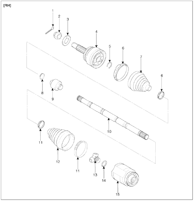
- Split pin
- Castle nut
- Washer
- BJ assembly
- Clip A
- Ð’J boot band
- Ð’J boot band
- Dynamic damper band
- Dynamic damper
- Shaft
- VTJ boot band
- VTJ boot
- Spider assembly
- Circlip
- VTJ housing
Repair procedures
Replacement
1. Loosen the wheel nuts slightly.
Raise the vehicle, and make sure it is securely supported.
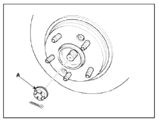
2. Remove the front wheel and tire (A) from front hub.
Tightening torque: 88.3 ~ 107.8N.m (9.0 ~ 11.0kgf.m, 65.0 ~ 79.5lb-ft)
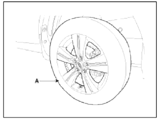
CAUTION
Be careful not to damage to the hub bolts when removing the front wheel and tire (A).
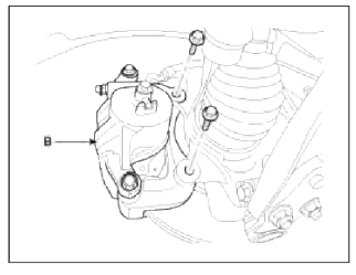
3. Remove the brake caliper mounting bolts, and then hold the brake caliper assembly (B) with wire.
Tightening torque: 78.4 ~ 98.0N.m (8.0 ~ 10.0kgf.m, 57.8 ~ 72.3lb-ft)
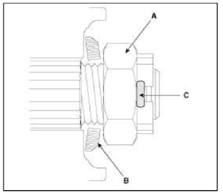
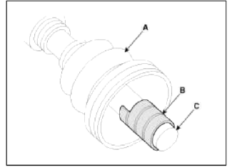
4. Remove castle nut (A) from the front hub.
Tightening torque: 196.1 ~ 274.5N.m (20.0 ~ 28.0kgf.m, 144.6 ~ 202.5lb-ft)
CAUTION
The washer (B) should be assembled with convex surface outward when installing the castle nut (A) and split pin (C) Also, don't reuse split pin (C) when reassembling.
5. Remove the brake hose (A) and wheel speed sensor (B).
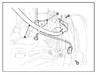
Tightening torque: 6.8 ~ 10.8N.m (0.7 ~ 1.1kgf.m, 5.1 ~ 7.9lb-ft)
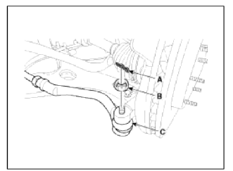
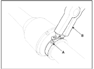
6. Remove the tie rod end ball joint (C) from the knuckle.
- Remove the split pin (A).
- Remove the castle nut (B).
Tightening torque: 34.3 ~ 44.1N.m (3.5 ~ 4.5kgf.m, 25.3 ~ 32.5lb-ft)
CAUTION
Apply a few drops of oil to the special tool. (Boot contact part)
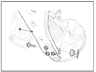
7. Remove the lower arm (A) mounting bolt from the knuckle.
Tightening torque: 98.0 ~ 117.6N.m (10.0 ~ 12.0kgf.m 72.3 ~ 86.7lb-ft)
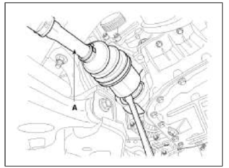
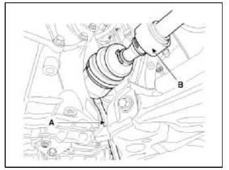
8. Disconnect the drive shaft end (A) from the knuckle.
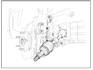
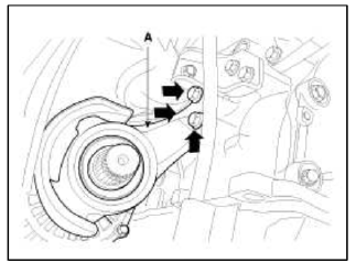
9. Remove the driveshaft assembly (A) from the inner shaft.
10. Remove the inner shaft mounting bolts and then disconnect the inner shaft (A).
11. Insert a pry bar (A) between the transaxle case and joint case, and separate the driveshaft (B) from the the transaxle case.
12. Install in the reverse order of removal.
CAUTION
- Use a pry bar (A) being careful not to damage the transaxle and joint.
- Do not insert the pry bar (A) too deep, as this may cause damage to the oil seal.
- Do not pull the driveshaft by excessive force it may cause components inside the joint kit to dislodge resulting in a tom boot or a damaged bearing.
- Plug the hole of the transaxle case with the oil seal cap to prevent contamination.
- Support the driveshaft properly.
- Replace the retainer ring whenever the driveshaft is removed from the transaxle case.
Inspection
1. Check the driveshaft boots for damage and deterioration.
2. Check the ball joint for wear and damage.
3. Check the splines for wear and damage.
4. Check the dynamic damper for cracks, wear and position.
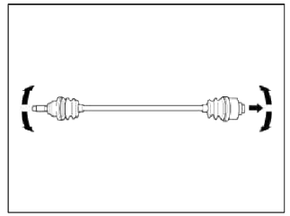
5. Check the driveshaft for cracks and wears.
Disassembly
CAUTION
- Do not disassemble the BJ assembly.
- Special grease must be applied to the driveshaft joint. Do not substitute with another type of grease.
- The boot band should be replaced with a new one.
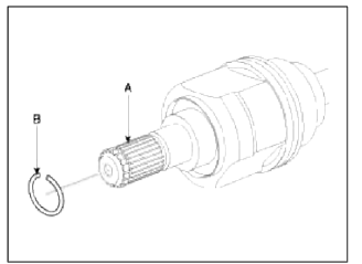
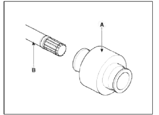
1. Remove the circlip (B) from driveshaft splines (A) of the transaxle side VTJ case.
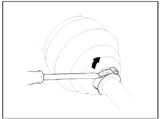
2. Remove the both boot clamps from the transaxle side VTJ case. Using a flat-tipped (-) screwdriver, remove the both clamps of the transaxle side.
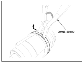
3. Pull out the boot from the transaxle side joint (VTJ).
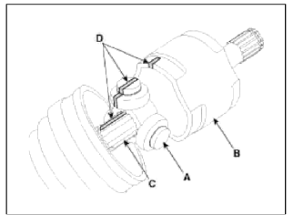
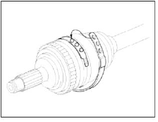
4. While dividing joint boot (A) of the transaxle side, wipe the grease in VTJ case (B) and correct them respectively.
CAUTION
- Be careful not to damage the boot.
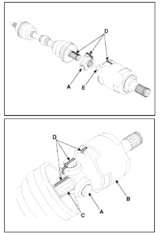
- According to below the illustrated, put marks (D) on roller of spider assembly (A), VTJ case (B) and spline part (C), to assist in re-assembly.
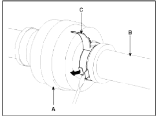
5. Using a snap ring plier or flat-tipped (-) screwdriver, remove the circlip (A).
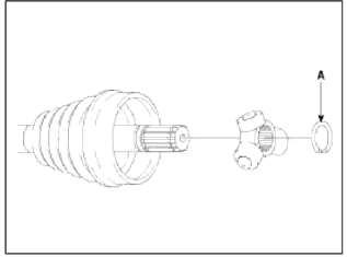
6. Clean the spider assembly.
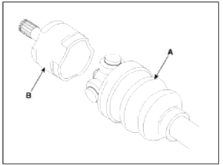
7. Remove the boot (A) of the transaxle side joint (VTJ).
8. Using a plier or flat-tipped (-) screwdriver, remove the clamp (B) of the dynamic damper (A).
9. Fix the driveshaft (A) with a vice (B) as illustrated.
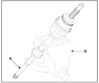
10. Apply soap powder on the shaft to prevent being damaged between the shaft spline and the dynamic damper when the dynamic damper is removed.
11. Separate the dynamic damper (A) from the shaft (B) carefully.
12. Using a plier or flat-tipped (-) screwdriver, remove the clamp on the side of wheel.
13. Pull out the joint (BJ) on the side of wheel into the transaxle direction. Be careful not to damage the boot.
Reassembly
1. Wrap tape around the driveshaft splines (VTJ side) to prevent damage to the boots.
2. Apply grease to the driveshaft and install the Ð’J boots.
3. Install the bands to both Ð’J boots.
4. To reassemble the dynamic damper (A), keeping the shaft (B) in the straight line. Tighten the dynamic damper (A) with dynamic damper band (C), as the illustration.
5. Install the VTJ boot bands and VTJ boot.
6. Install the spider assembly (A) and the circlip (E) to the spline (C) on the driveshaft.
At this time align the marks (D) each other.
7. Install the clip to the VTJ case (B).
8. Add the specified grease to the VTJ as mush as wiped away at inspection.
9. Install the VTJ boots.
10. Install the bands to both VTJ boots.
11. Using the SST (09495-3K000), secure the boot bands.
Clearance (A): 2.0 mm (0.079 in.) or less
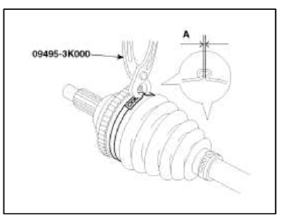
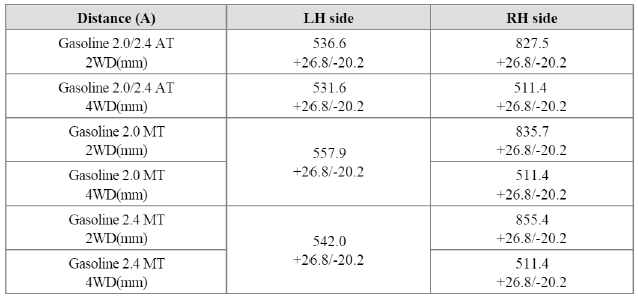
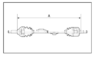
12. To control the ah in the VTJ boot, keep the specified distance between the boot bands when they are tightened.
READ NEXT:
 Rear Axle Assembly
Rear Hub - Carrier
Components and Components
Location
Components
(2WD) / (4WD)
Hub cover
Carrier assembly
Hub & bearing
assembly
Hub mounting bolt
Bushing
Bushing
Car
SEE MORE:
Rear Door
Components and Components Location
Components
Rear door trim
Rear door inside handle cap
Rear door belt inside weatherstrip
Rear door trim seal
Rear door module
Rear door panel
Rear door belt weatherstrip
Rear door frame garnish
Rear door body side weatherstrip
Rear do
Specifications, Components and Components Location, Description and Operation | Auto Light Sensor
Specifications
Specifications
Components and Components Location
Component Location
Auto light sensor
Head lamps
Lighting switch (Auto)
Tail lamps
SJB (Smart Junction Box)
BCM (Body Control Module)
Schematic Diagrams
Circuit Diagram
Content
- Home
- Kia Sportage - Fifth generation (NQ5) - (2022-2026) - Owner's Manual
- Kia Sportage - Second generation (JEKM) (2005-2015) - Body Workshop Manual
- Kia Sportage Third generation (SL) - (2011-2016) - Service and Repair Manual
- Sitemap
- Top articles
