Kia Sportage: Front Axle Assembly
Front Hub / Knuckle / Tone Wheel
Components and Components Location
Components
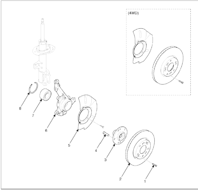
- Brake disc screw
- Brake disc
- Hub
- Hub bolt
- Dust cover
- Knuckle
- Wheel bearing
- Snap ring
Repair procedures
Replacement
1. Loosen the wheel nuts slightly.
Raise the vehicle, and make sure it is securely supported.
2. Remove the front wheel and tire (A) from front hub.
Tightening torque: 88.3 ~ 107.8N.m (9.0 ~ 11.0kgf.m, 65.0 ~ 79.5lb-ft)
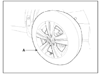
CAUTION
Be careful not to damage to the hub bolts when removing the front wheel and tire (A).
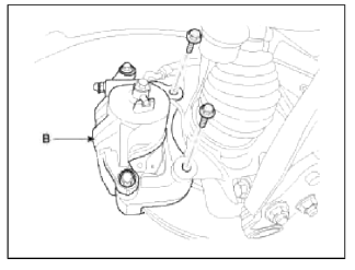
3. Remove the brake caliper mounting bolts, and then hold the brake caliper assembly (B) with wire.
Tightening torque: 78.4 ~ 98.0N.m (8.0 ~ 10.0kgf.m, 57.8 ~ 72.3lb-ft)
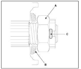
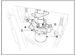
4. Remove castle nut (A) from the front hub.
Tightening torque: 196.1 ~ 274.5N.m (20.0 ~ 28.0kgf.m, 144.6 ~ 202.5lb-ft)
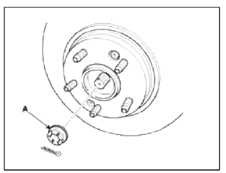
CAUTION
The washer (B) should be assembled with convex surface outward when installing the castle nut (A) and split pin (C) Also, don't reuse split pin (C) when reassembling.
5. Remove the brake hose (A) and wheel speed sensor (B).
Tightening torque: 6.8 ~ 10.8N.m (0.7 ~ 1.1kgf.m, 5.1 ~ 7.9lb-ft)
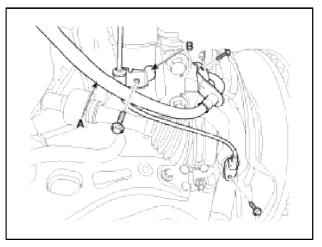
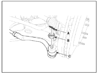
6. Remove the tie rod end ball joint (C) from the knuckle.
- Remove the split pin (A).
- Remove the castle nut (B).
Tightening torque: 34.3 ~ 44.1N.m (3.5 ~ 4.5kgf.m, 25.3 ~ 32.5lb-ft)
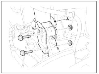
7. Remove the lower arm (A) mounting bolt and nut from the knuckle.
Tightening torque: 98.0 ~ 117.6N.m (10.0 ~ 12.0kgf.m 72.3 ~ 86.7lb-ft)
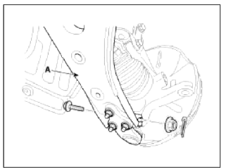
8. Disconnect the drive shaft end (A) from the knuckle.
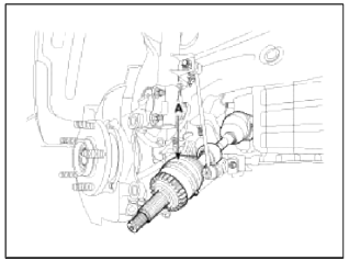
9. Loosen the stint mounting bolts and then remove the hub and knuckle assembly from the shut assembly (A).
Tightening torque: 137.2 ~ 156.9N.m (14.0 ~ 16.0kgf.m, 101.2 ~ 115.7lb-ft)
CAUTION
Be careful not to damage the boot and rotor teeth.
1. Install in the reverse order of removal.
Inspection
1. Check the hub for cracks and the splines for wear.
2. Check the brake disc for scoring and damage.
3. Check the knuckle for cracks.
4. Check the bearing for cracks or damage.
Disassembly
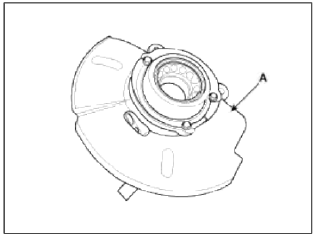
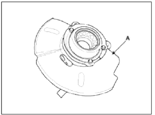
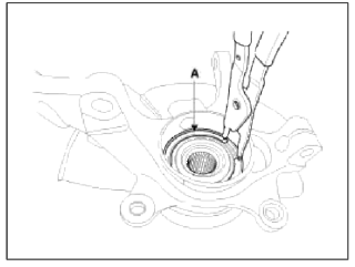
1. Using the snap ring pliers, remove the snap ring (A).

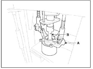
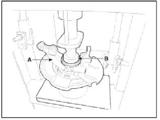
2. Remove the hub assembly from the knuckle assembly.
- Install the front knuckle assembly (A) on press.
- Lay a suitable adapter (B) upon the hub assembly shaft.
3. Remove the dust cover (A).
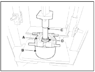
4. Remove the hub bearing inner race from the hub assembly
- Install a suitable tool (A) for removing the hub bearing inner race on the hub assembly.
- Lay the hub assembly and tool (A) upon a suitable adapter (B).
- Lay a suitable adapter (C) upon the hub assembly shaft.
- Remove the hub bearing inner race (D) from the hub assembly by using press.
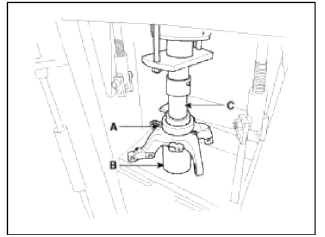
5. Remove the hub bearing outer race from the knuckle assembly.
- Lay the hub assembly (A) upon a suitable adapter (B).
- Lay a suitable adapter (C) upon the hub bearing outer race.
- Remove the hub bearing outer race from the knuckle assembly by using press
6. Replace hub bearing with a new one.
Reassembly
1. Install the dust cover (A).
2. Install the hub bearing to the knuckle assembly.
- Lay the knuckle assembly (A) on press.
- Lay a new hub bearing upon the knuckle assembly (A).
- Lay a suitable adapter (B) upon the hub bearing.
- Install the hub bearing to the knuckle assembly by using press.
CAUTION
Do not press against the inner race of the hub bearing because that can cause damage to the bearing assembly.
Always use a new wheel bearing assembly.
3. Install the hub assembly to the knuckle assembly.
- Lay the hub assembly (A) upon a suitable adapter (B).
- Lay the knuckle assembly (C) upon the hub assembly (A).
- Lay a suitable adapter (D) upon the hub bearing.
- Install the hub assembly (A) to the knuckle assembly (C) by using press.
CAUTION
Do not press against the inner race of the hub bearing because that can cause damage to the bearing assembly.
4. Install the snap ring (A).
READ NEXT:
 Components and ComponentsLocation | Repair procedures
Components
Front driveshaft (LH)
Inner shaft
Front driveshaft (RH)
[LH]
Split pin
Castle nut
Washer
BJ assembly
Clip A
Ð’J boot ban
SEE MORE:
Yaw-rate and Lateral G Sensor | ESC OFF Switch
Description and Operation
Description
When the vehicle is turning with respect to a vertical axis the yaw rate sensor detects the yaw rate electronically by the vibration change of plate fork inside the yaw rate sensor.
If yaw velocity reaches the specific velocity after it detects the veh
Owner maintenance
The following lists are vehicle checks
and inspections that should be performed
by the owner or an authorized
Kia dealer at the frequencies indicated
to help ensure safe, dependable operation
of your vehicle.
Any adverse conditions should be
brought to the attention of your dealer
as soon
Content
- Home
- Kia Sportage - Fifth generation (NQ5) - (2022-2026) - Owner's Manual
- Kia Sportage - Second generation (JEKM) (2005-2015) - Body Workshop Manual
- Kia Sportage Third generation (SL) - (2011-2016) - Service and Repair Manual
- Sitemap
- Top articles
