Kia Sportage: Intake Actuator
Components and Components Location
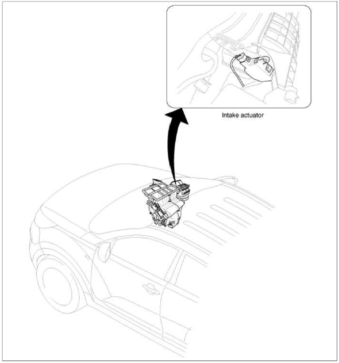
Component Location
Description and Operation
Description
1. The intake actuator is located at the blower unit.
2. It regulates the intake door by signal from control unit.
3. Pressing the intake selection switch will shift between recirculation and fresh air modes.
Repair procedures
Inspection
1. Ignition "OFF"
2. Disconnect the intake actuator connector.
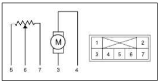
3. Verify that the actuator operates to the recirculation position when connecting 12V to the terminal 3 and grounding terminal 4.
4. Verify that the intake actuator operates to the fresh position when connecting in the reverse.
- -
- -
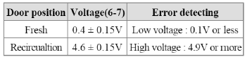
- Fresh
- Recirculation
- 5V (Vcc)
- Feedback Signal
- Sensor Ground
5. Check the voltage between terminals 6 and 7.
6. If the intake actuator is not operated well, substitute with a known-good intake actuator and check for proper operation.
7. If the problem is corrected, replace the intake actuator.
Replacement
1. Disconnect the negative (-) battery terminal.
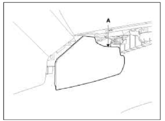
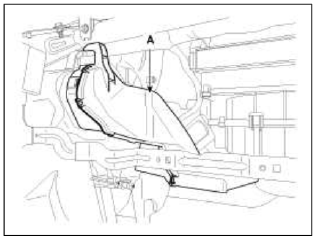
2. Remove the right extension cover (A).
3. Remove the crash pad.
(Refer to BD group - "Crash Pad")
4. Remove the right shower duct (A).
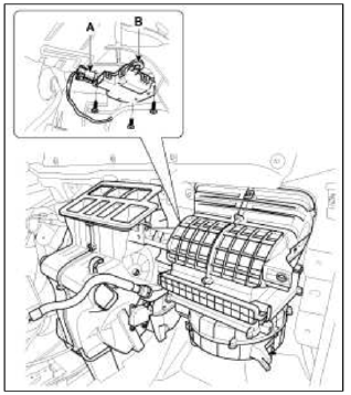
5. Disconnect the Intake actuator connector (A).
6. Loosen the mounting screw and then remove the intake actuator (B).
7. Installation is the reverse order of removal.
READ NEXT:
 Heater & A/C Control Unit (Manual, Full Automatic)
Components and Components Location
Components
Connector Pin Function
Repair procedures
Replacement
1. Disconnect the negative (-) battery terminal.
2. Using the screwdriver, remove t
SEE MORE:
Components and ComponentsLocation | Removal - Repair procedures
Components (1)
[Hand Type] / [Foot Type]
Parking brake pedal assembly
Front parking brake cable (Foot type only)
Equalizer assembly
Rear parking brake cable
Parking brake lever assembly
Components (2)
[2WD]
Backing plate
Brake shoe
Sh
Turbo Charger
Components and
Components Location
Components
Turbine housing
Turbine inlet
Turbine outlet
Compressor housing
Compressor inlet
Compressor outlet
Center housing
EWGA (Electric Waste Gate Actuator)
Actuator rod
Repair procedures
On-vehicle Inspection
Turbocharg
Content
- Home
- Kia Sportage - Fifth generation (NQ5) - (2022-2026) - Owner's Manual
- Kia Sportage - Second generation (JEKM) (2005-2015) - Body Workshop Manual
- Kia Sportage Third generation (SL) - (2011-2016) - Service and Repair Manual
- Sitemap
- Top articles
