Kia Sportage: Knock Sensor (KS) | Heated Oxygen Sensor (HO2S)
Description and Operation
Description
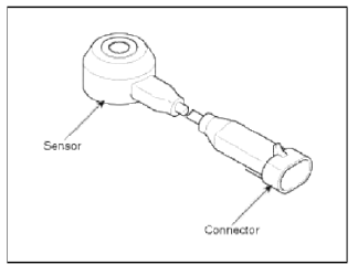
Knocking is a phenomenon characterized by undesirable vibration and noise and can cause engine damage. Knock Sensor (KS) is installed on the cylinder block and senses engine knocking.
When knocking occurs, the vibration from the cylinder block is applied as pressure to the piezoelectric element.
When a knock occurs, the sensor produces voltage signal. The ECM retards the ignition timing when knocking occurs. If the knocking disappears after retarding the ignition timing, the ECM will advance the ignition timing. This sequential control can improve engine power, torque and fuel economy.
Specifications
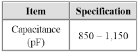
Specification
Schematic Diagrams
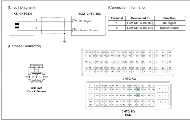
Circuit Diagram
Repair procedures
Removal
1. Turn the ignition switch OFF and disconnect the battery negative (-) cable.
2. Remove the intake manifold (Refer to "Intake And Exhaust System" in EM group).
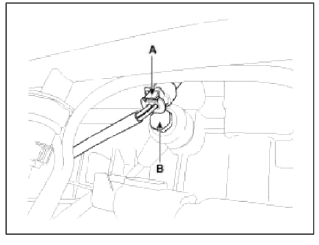
3. Disconnect the knock sensor connector (A).
4. Remove the installation bolt (B), and then remove the sensor from the cylinder block
Installation
CAUTION
- Install the component with the specified torques.
- Note that internal damage may occur when the component is dropped. If the component has been dropped, inspect before installing.
1. Installation is reverse of removal.
Knock sensor installation bolt: 18.6 ~ 23.5 N.m (1.9 ~ 2.4 kgf.m, 13.7 ~ 17.4 lb-ft)
Heated Oxygen Sensor (HO2S)
Description and Operation
Description
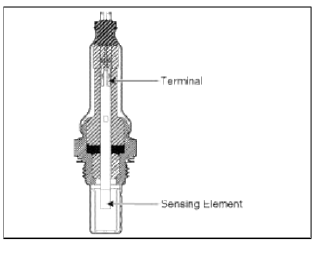
Heated Oxygen Sensor (HO2S) consists of zirconium and alumina and is installed both upstream and downstream of the Manifold Catalytic Converter. The sensor output voltage varies in accordance with the air/fuel ratio.
The sensor must be hot in order to operate normally. To keep it hot, the sensor has a heater which is controlled by the ECM via a duty cycle signal. When the exhaust gas temperature is lower than the specified value, the heater warms the sensor tip.
Specifications
Specification
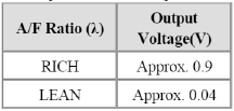
HO2S [Bank 1 / Sensor 1]
![HO2S [Bank 1 / Sensor 2]](images/books/1921/21/index%20148.png)
HO2S [Bank 1 / Sensor 2]
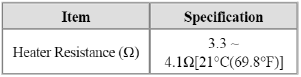
Schematic Diagrams
Circuit Diagram
Repair procedures
Inspection
1. Turn the ignition switch OFF.
2. Disconnect the HO2S connector.
3. Measure resistance between the HO2S terminals 4 and 5 [B1/S1].
4. Measure resistance between the HO2S terminals 3 and 4 [B1/S2].
5. Check that the resistance is within the specification.
Specification: Refer to "Specification"
Removal
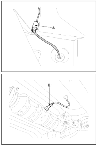
[Bank 1 / Sensor 1]
1. Turn the ignition switch OFF and disconnect the battery negative (-) cable.
2. Disconnect the connector (A), and then remove the sensor (B).
NOTE
Note that the SST (Part No.: 09392-2H100) is useful when removing the heated oxygen sensor.
![[Bank 1 / Sensor 2]](images/books/1921/21/index%20152.png)
[Bank 1 / Sensor 2]
1. Turn the ignition switch OFF and disconnect the battery negative (-) cable.
2. Remove the console side cover (A).

З. Disconnect the connector (A), and then remove the sensor (B).
NOTE
Note that the SST (Part No.: 09392-2H100) is useful when removing the heated oxygen sensor.
Installation
CAUTION
- Install the component with the specified torques.
- Note that internal damage may occur when the component is dropped, hr this case, use it after inspecting.
CAUTION
- DON'T use a cleaner, spray, or grease to sensing element and connector of the sensor because oil component in them may malfunction the sensor performance.
- Sensor and its wiring may be damaged in case of contacting with the exhaust system (Exhaust Manifold, Catalytic Converter, and so on).
1. Installation is reverse of removal.
Heated oxygen sensor installation [Bank 1/Sensor1]: 39.2 ~ 49.1 N.m (4.0 ~ 5.0 kgf.m, 28.9 ~ 36.2 lb-ft)
Heated oxygen sensor installation [Bank 1/Sensor2]: 39.2 ~ 49.1 N.m (4.0 ~ 5.0 kgf.m, 28.9 ~ 36.2 lb-ft)
READ NEXT:
 Rail Pressure Sensor (RPS)
Description and Operation
Description
Rail Pressure Sensor (RPS) is installed on the delivery pipe and measures the
instantaneous fuel pressure in the delivery pipe. The sensing element
(S
CVVT Oil Temperature Sensor (OTS)
Description and
Operation
Description
Continuous Variable Valve Timing (CVVT) system advances or retards the valve
tuning of the intake and exhaust
valve in accordance with the ECM control
SEE MORE:
Brake Line
Components and Components Location
Components
Repair procedures
Removal
1. Disconnect the brake fluid level switch connector, and remove the
reservoir cap.
2. Remove the brake fluid from the master cylinder reservoir with a syringe.
CAUTION
Do not spill brake fluid on the vehicle,
Inspection - Repair procedures
Connecting Rod
1. Check the connecting rod end play.
Using a feeler gauge, measure the end play while moving the connecting rod back
and forth.
End play:
Standard : 0.10 ~ 0.25mm (0.0039 ~ 0.0098in.)
Limit: 0.35mm (0.0138in.)
If out-of-tolerance, install a new connecting rod.
If sti
Content
- Home
- Kia Sportage - Fifth generation (NQ5) - (2022-2026) - Owner's Manual
- Kia Sportage - Second generation (JEKM) (2005-2015) - Body Workshop Manual
- Kia Sportage Third generation (SL) - (2011-2016) - Service and Repair Manual
- Sitemap
- Top articles
