Kia Sportage: Specifications, Components and Components Location | Audio Unit
Specifications
Specifications
Audio
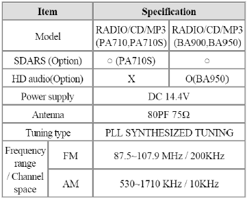
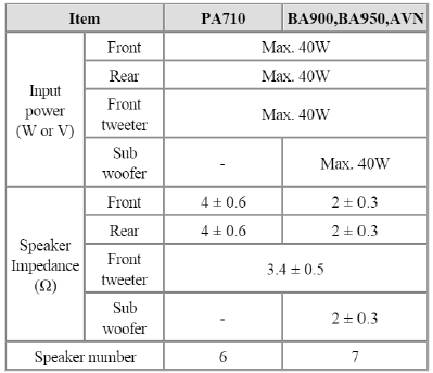
Speaker
Components and Components Location
Component Location
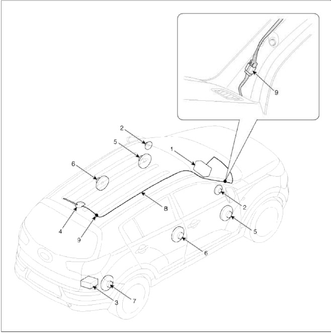
- Audio unit
- Tweeter speaker
- External amplifier
- Roof antenna (Radio)
- Front door speaker
- Rear door speaker
- Sub woofer speaker
- Antenna feeder cable
- Antenna cable connector
Audio Unit
Components and Components Location
Components
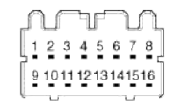
[RADIO/CD/MP3 (PA710/PA710S) ]
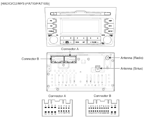
Connector A
- Speaker RL (+)
- Speaker FL (+)
- Speaker FR (+)
- Speaker RR (+)
- SPDIF GND
- SPDIF DN
- IGN
- Illumination (+)
- DETENT
- Speaker RL (-)
- Speaker FL (-)
- Speaker FR (-)
- Speaker RR (-)
- Remote AMP
- SPDIF DP
- E.AMP MUTE
- Illumination (-)
- Remote Antenna
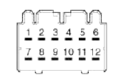
Connector Ð’
- CAN-H
- TEL MUTE
- TEMP
- Steering remote
- -
- USB D (+)
- USB/iPod VDD
- AUX Input R
- AUX GND
- Mic (+)
- ACC
- Battery (+)
- CAN-L
- -
- -
- Vehicle speed
- Remote GND
- USB D (-)
- USB/iPod GND
- AUX Detect
- AUX Input L
- Mic (-)
- -
- Power GND
[RADIO/CD/MP3 (BA900/BA950) - External Amplifier]
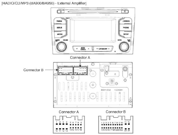
Connector A
- Speaker RL (+)
- Speaker FL (+)
- Speaker FR (+)
- Speaker RR (+)
- -
- -
- Ignition
- Illumination (+)
- -
- Speaker RL (-)
- Speaker FL (-)
- Speaker FR (-)
- Speaker RR (-)
- P position
- -
- -
- Illumination (-)
- Remote antenna
Connector Ð’
- CAN-H
- -
- -
- Steering remote
- -
- Camera_V_IN
- Camera B+
- AUX_R_IN
- AUX_REF
- MIC+(BT)
- ACC
- B/UP
- CAN-L
- -
- Auto light
- Speed IN
- Remote GND
- Camera V_GND
- Camera REQ
- AUX_Detect
- AUX_L_IN
- MIC-(BT)
- Camera_P_GND
- Power GND
[RADIO/CD/MP3 (BA900/BA950) - Internal Amplifier]
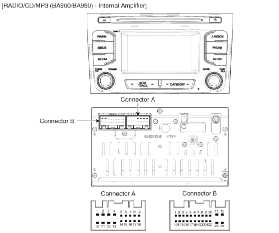
Connector A
- -
- -
- -
- -
- SPDIF GND
- SPDIF DN
- Ignition
- Illumination (+)
- -
- -
- -
- -
- -
- P position
- SPDIF DP
- -
- Illumination (-)
- Remote antenna
Connector Ð’
- CAN-H
- -
- -
- Steering remote
- -
- Camera_V_IN
- Camera B+
- AUX_R_IN
- AUX_REF
- MIC+(BT)
- ACC
- B/UP
- CAN-L
- -
- Auto light
- Speed IN
- Remote GND
- Camera V_GND
- Camera REQ
- AUX_Detect
- AUX_L_IN
- MIC-(BT)
- Camera_P_GND
- Power GND
[External Amplifier]
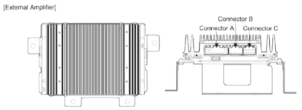
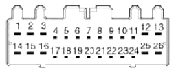 Connector A
- B (+)
- B (+)
- B (+)
- -
- CAN (+)
- CAN (-)
- ACC
- -
- -
- -
- Navigation (+)
- Sub woofer 2 (+)
- Sub woofer 1 (+)
- GND
- GND
- GND
- -
- SPDIF (+)
- SPDIF (-)
- -
- -
- -
- -
- Navigation (-)
- Sub woofer 2 (-)
- Sub woofer 1 (-)
 Connector B
- -
- -
- -
- -
- -
- -
- -
- -
- -
- -
- -
- -
- -
- -
- -
- -
 Connector C
- Rear Door Right (+)
- Rear Door Left (+)
- Front Tweeter Right (+)
- Front Tweeter Left (+)
- Front Door Right (+)
- Front Door Left (+)
- Rear Door Right (-)
- Rear Door Left (-)
- Front Tweeter Right (-)
- Front Tweeter Left (-)
- Front Door Right (-)
- Front Door Left (-)
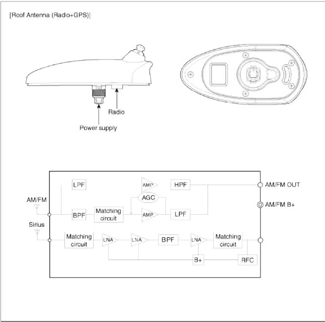
[Roof Antenna (Radio) ]
![[Roof Antenna (Radio+GPS) ]](images/books/1921/7/index%208.png)
[Roof Antenna (Radio+GPS) ]
Repair procedures
Removal
1. Disconnect the negative (-) battery terminal.
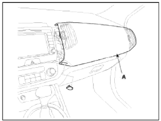
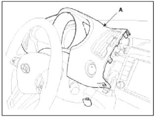
2. Remove the crash pad passenger's garnish (A).
(Refer to BD group - "Crash pad")
3. Disconnect the connectors and remove the cluster fascia panel (A).
(Refer to BD group - "Crash pad")
4. Remove the center fascia panel (A) after loosening the mounting screw (2EA).
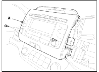
5. Disconnect the connector (A) installed on the center fascia panel.
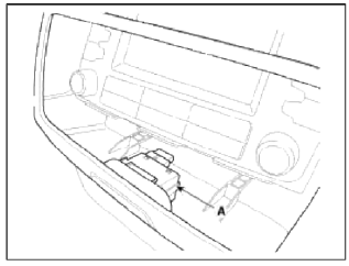
6. Remove the audio assembly (A) after loosening the mounting screw (4EA).
7. Disconnect the audio connectors and cable (A), then remove the audio unit completely.
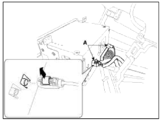
NOTE
Lift the connector locking clip to the arrow direction, disconnect the connector.
When assembling, install the connector and connector locking clip.
CAUTION
- If CD does not eject, don't try to remove it.
- The player may be damaged.
- Therefore, contact a service shop for repairs
Installation
1. Connect the audio unit connectors and cable.
2. Install the audio unit.
3. Install the center fascia panel.
4. Install the cluster fascia panel.
5. Install the crash pad passenger's garnish.
6. Connect the negative (-) battery terminal.
NOTE
- Make sure the connector are connected in properly.
- Check the audio system.
Disassembly
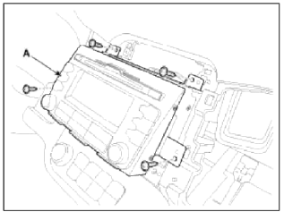
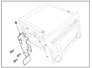
1. Loosen the screw (Left 3EA. Right 3EA) and remove the audio head unit mounting bracket (A).
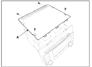
2. When separate the CD rom drive, if necessary, remove the top cover (A) after loosening the screws (4EA).
3. After loosening the screws, remove the CD rom drive (B).
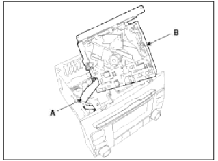
NOTE
Take care not to damage the cable connectors (A) when removing drive.
READ NEXT:
 Speakers
Repair procedures
Inspection
1. Troubleshooting for Speaker
Basic inspection of speaker
Inspect the sound from speaker after verifying that the speaker mounting
screws are removed
Antenna | Audio Remote Control
Repair procedures
Inspection
Antenna Cable
1. Remove the antenna jack from the audio unit and antenna.
2. Check for continuity between the center poles of antenna cable.
3. Check for cont
SEE MORE:
General Information, Troubleshooting, Special Service Tools
General Information
Specification
Air Conditioner
Blower Unit
Heater And Evaporator Unit
Troubleshooting
Troubleshooting
Problem Symptoms Table
Before replacing or repairing air conditioning components, first determine if
the malfunction is due to the refrigerant
charge,
Wipers and washers
The wipers and washers remove foreign
substances from the windshield and rear
window, helping to maintain visibility.
A: Wiper speed control
MIST - Single wipe
OFF - Off
INT - Intermittent wipe
AUTO* - Auto control wipe
LO - Low wiper speed
HI - High wiper speed
B: Interm
Content
- Home
- Kia Sportage - Fifth generation (NQ5) - (2022-2026) - Owner's Manual
- Kia Sportage - Second generation (JEKM) (2005-2015) - Body Workshop Manual
- Kia Sportage Third generation (SL) - (2011-2016) - Service and Repair Manual
- Sitemap
- Top articles
