Kia Sportage: Components and ComponentsLocation | Disassembly - Repair procedures
Components
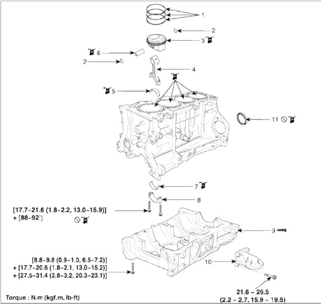
- Piston ring
- Snap ring
- Piston
- Connecting rod
- Connecting rod upper bearing
- Piston pin
- Connecting rod lower bearing
- Connecting rod bearing cap
- Ladder frame
- Oil filter bracket
- Crankshaft rear oil seal
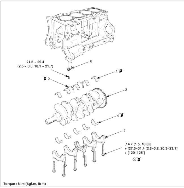
- Crankshaft upper bearing
- Thrust bearing
- Crankshaft
- Crankshaft lower bearing
- Main bearing cap
- Piston cooling oil jet
Disassembly - Repair procedures
CAUTION
- Use fender covers to avoid damaging painted surfaces.
- To avoid damage, unplug the wiring connectors carefully while holding the connector portion.
NOTE
- Mark all wiring and hoses to avoid misconnection.
- Turn the crankshaft pulley so that the No.1 piston is at top dead center.
- Engine removal is required for this procedure.
WARNING
In case of removing the high pressure fuel pump, high pressure fuel pipe, delivery pipe, and injector, there may be injury caused by leakage of the high pressure fuel. So don't do any repair work right after engine stops.
1. Remove the engine assembly from the vehicle. (Refer to Engine and transaxle assembly in this group)
2. Install the engine to an engine stand for disassembly.
3. Remove the intake manifold and exhaust manifold. (Refer to Intake and exhaust system in this group)
4. Remove the timing chain. (Refer to Timing system in this group)
5. Remove the cylinder head assembly. (Refer to Cylinder head in this group)
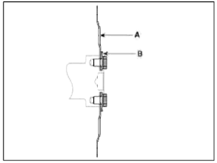
6. Remove the drive plate (A) and the adapter plate (B).
7. Remove the balance shaft & oil pump assembly. (Refer to Lubrication system in this group)
8. Remove the Ð/С compressor. (Refer to HA group)
9. Remove the alternator. (Refer to EE group)
10. Remove the water pump assembly. (Refer to Cooling system in this group)
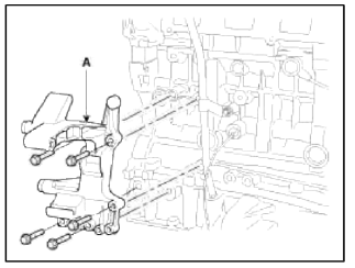
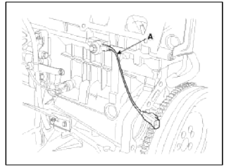
11. Remove the tensioner assembly integrated bracket (A).
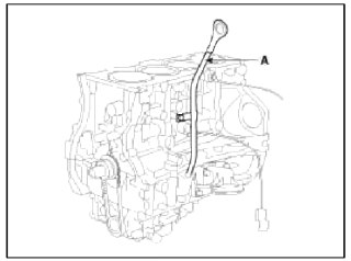
12. Remove the oil level gauge tube (A).
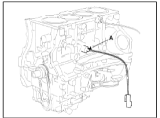
13. Remove the knock sensor (A).
14. Remove the oil pressure sensor (A).
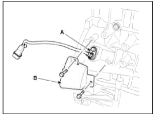
15. Remove the cover (B) and then CKPS (Crankshaft position sensor) (A).
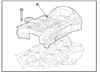
16. Remove the ladder frame (A).
17. Check the connecting rod end play.
18. Remove the connecting rod caps and check oil clearance.
19. Remove piston and connecting rod assemblies.
- Using a ridge reamer, remove all the car bon from the top of the cylinder.
- Push the piston, connecting rod assembly and upper bearing though the top of the cylinder block.
NOTE
- Keep the bearings, connecting rod and cap together.
- Arrange the piston and connecting rod assemblies in the correct order.
20. Remove crankshaft bearing cap and check oil clearance.
21. Check the crankshaft end play.
22. Lift the crankshaft (A) out of the engine, being careful not to damage journals.
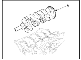
NOTE
Arrange the main bearings and thrust bearings in the correct order.
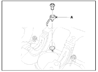
23. Remove the oil jet (A).
24. Check fit between piston and piston pin.
Try to move the piston back and forth on the piston pin. If any movement is felt, replace the piston and pin as a set.
25. Remove piston lings.
- Using a piston ring expander, remove the 2 compression lings.
- Remove oil ring.
NOTE
Arrange the piston rings in the correct order only.
26. Disconnect connecting rod from piston.
Remove the snap ring at both ends of piston pin. And push the piston pin to seperate and connecting rod.
READ NEXT:
 Inspection - Repair procedures
Connecting Rod
1. Check the connecting rod end play.
Using a feeler gauge, measure the end play while moving the connecting rod back
and forth.
End play:
Standard : 0.10 ~ 0.25mm (0.0039 ~ 0.0
Reassembly - Repair procedures
NOTE
Thoroughly clean all parts to assembled.
Before installing the parts, apply fresh engine oil to all sliding
and rotating surfaces.
Replace all gaskets, O-rings and oil seals with new p
SEE MORE:
Blade inspection
When the wipers no longer clean adequately,
the blades may be worn or
cracked, and require replacement.
To prevent damage to the wiper arms or
other components, do not attempt to
move the wipers manually.
The use of a non-specified wiper blade
could result in wiper malfunction and
failur
Smart Cruise Control conditions not satisfied
A: Smart Cruise Control conditions not
met
If the Driving Assist button, + switch, -
switch or ( 3) switch is operated when
Smart Cruise Control's operating conditions
are not satisfied, a warning message
will appear on the cluster, and an
audible warning will sound.
In traffic situa
Content
- Home
- Kia Sportage - Fifth generation (NQ5) - (2022-2026) - Owner's Manual
- Kia Sportage - Second generation (JEKM) (2005-2015) - Body Workshop Manual
- Kia Sportage Third generation (SL) - (2011-2016) - Service and Repair Manual
- Sitemap
- Top articles
