Kia Sportage: Installation - Repair procedures - Cylinder Head
Installation
NOTE
- Thoroughly clean all parts to be assembled.
- Always use a new head and manifold gasket.
- The cylinder head gasket is a metal gasket. Take care not to bend it.
- Rotate the crankshaft, set the No.1 piston at TDC.
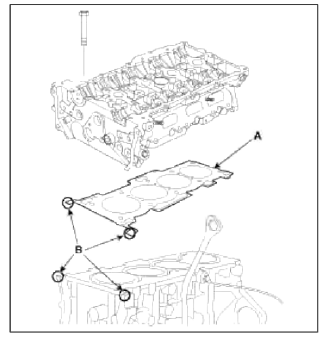
1. Install the cylinder head gasket (A) on the cylinder block
NOTE
- Be careful of the installation direction.
- Apply liquid gasket (Loctite 5900H or equivalent) on the edge of cylinder head gasket upside and downside. (At the position 'B')
- After applying sealant, assemble the cylinder head in five minutes.
2. Place the cylinder head carefully in order not to damage the gasket with the bottom part of the end.
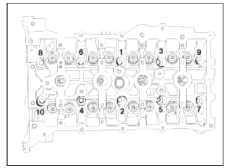
3. Install cylinder head bolts.
- Do not apply engine oil on the the cylinder head bolts.
- Using the SST (09221-4A000), tighten the cylinder head bolts and plate washers, in several passes, in the sequence shown.
Tightening torque: 32.4 ~ 36.3N.m (3.3~3.7kgf.m, 23.9~26.8lb-ft) + 90~95º + 90~95º
CAUTION
Always use new cylinder head bolt.
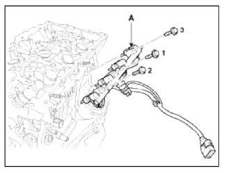
4. Install the injector & rail module (A). (Refer to FL group)
Pre-tighten the bolts and then tighten the bolts with the specified torque in the sequence shown.
Tightening torque: 18.6~23.5N.m (1.9~2.4kgf.m, 13.7 ~ 17.4lb-ft)
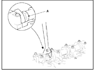
5. Install the intake CMPS (Camshaft position sensor) (A).
Tightening torque: 9.8 ~ 11.8N.m (1.0 ~ 1.2kgf.m, 7.2 ~ 8.7lb-ft)
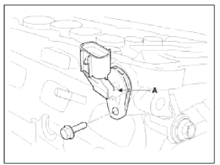
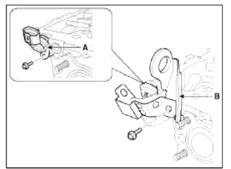
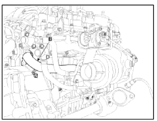
6. Install the exhaust CMPS (Camshaft position sensor) (A) and the engine hanger (B).
Tightening torque:
Sensor bolt: 9.8 ~ 11.8N.m (1.0 ~ 1.2kgf.m, 7.2 ~ 8.7lb-ft)
Hanger bolt: 27.5 ~ 31.4N.m (2.8 ~ 3.2kgf.m, 20.3 ~ 23.1lb-ft)
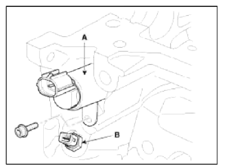
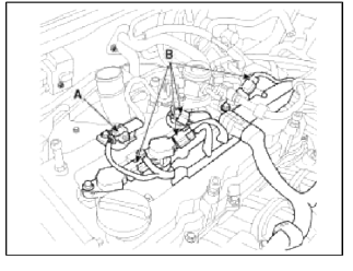
7. Install the intake OCV (Oil control valve) (A) and the OTS (Oil temperature sensor) (B).
Tightening torque:
OCV bolt: 9.8 ~ 11.8N.m (1.0 ~ 1.2kgf.m, 7.2 ~ 8.7lb-ft)
OTS: 19.6 ~ 23.5N.m (2.0 ~ 2.4kgf.m, 14.5 ~ 17.4lb-ft)
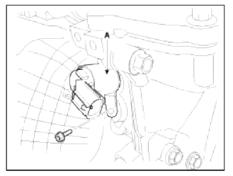
8. Install the exhaust OCV (Oil control valve) (A).
Tightening torque: 9.8 ~ 11.8N.m (1.0 ~ 1.2kgf.m, 7.2 ~ 8.7lb-ft)
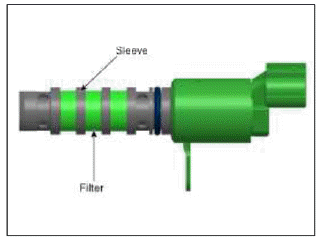
CAUTION
- Do not reuse the OCV when dropped.
- Keep the OCV and filter clean.
- Do not hold the OCV sleeve during servicing.
- When the OCV is installed on the engine, do not move the engine with holding the OCV yoke.
9. Install the camshafts.
NOTE
Apply a light coat of engine oil on camshaft journals.
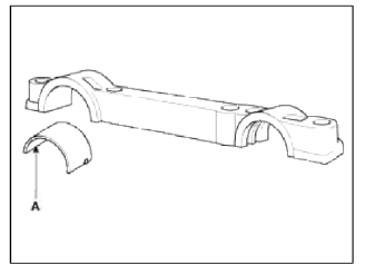
- Install the exhaust camshaft lower bearing (A).
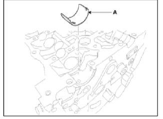
- Install the camshafts (A).
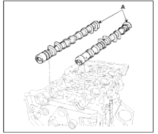
- Install the exhaust camshaft tipper bearing (A) to the front bearing cap.
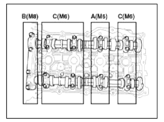
- Install camshaft bearing caps (A) in their proper locations.
Tightening order
Group A → Group В → Group C.
Tightening torque:
Step 1
M6 : 5.9N.m (0.6kgf.m. 4.3lb-ft)
M8 : 14.7N.m(1.5kgf.m, 10.8lb-ft)
Step 2
M6 : 10.8 ~ 12.7N.m (1.1 ~ 1.3kgf.m, 8.0 ~ 9.4lb-ft)
M8 : 27.5 ~ 31.4N.m (2.8 ~ 3.2kgf.m, 20.3 ~ 23.1lb-ft)
10. Install the intake CVVT assembly (A) and exhaust CVVT assembly (B).
Tightening torque: 53.9 ~ 63.7N.m (5.5 ~ 6.5kgf.m, 39.7 ~ 47.0lb-ft)
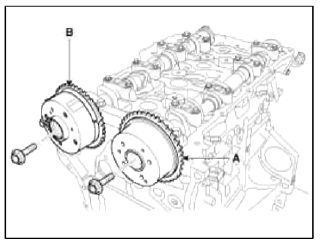
NOTE
When installing the CVVT assembly bolt, prevent the camshaft from rotating by using a wrench at position A.
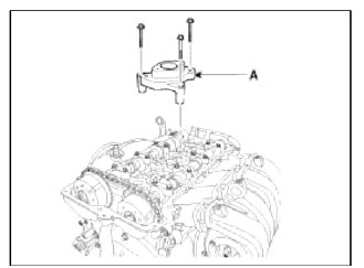
11. Install the high pressure fuel pump bracket (A).
Tightening torque: 18.6 ~ 23.5N.m (1.9 ~ 2.4kgf.m, 13.7 ~ 17.4lb-ft)
12. Install the intake and exhaust manifold. (Refer to Intake and exhaust system in this group)
13. Install the timing chain. (Refer to Timing system in tins group)
14. Check and adjust the valve clearance. (Refer to General information in this group)
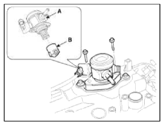
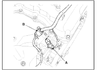
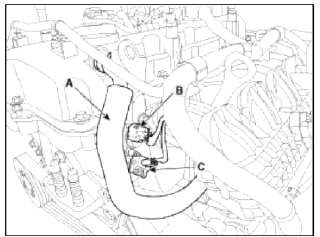
15. Install the water temperature control assembly (A) with the water inlet pipe (B).
Tightening torque:
Bolts: 14.7 ~ 19.6N.m (1.5 ~ 2.0kgf.m, 10.8 ~ 14.5lb-ft)
Nut: 18.6 ~ 23.5N.m (1.9 ~ 2.4kgf.m, 13.7 ~ 17.4lb-ft)
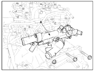
Tightening torque:
9.8 ~ 11.8N.m (1.0 ~ 1.2kgf.m, 7.2 ~ 8.7lb-ft)
NOTE
- Assemble water temp control assembly and water inlet pipe to water pump assembly before nuts for assembling of water inlet pipe to be tightened.
- Insert after wetting O-ring or inner surface of thermostat housing.
- Always use a new O-ring.
16. Install cylinder head cover.
- The hardening sealant located on the upper area between timing chain cover and cylinder head should be removed before assembling cylinder head cover.
- After applying sealant (Loctite 5900H or equivalent), it should be assembled within 5 minutes
Bead width : 2.5mm (0.10in.)
- Install the cylinder head cover (A) by tightening the bolts as following method.
Tightening torque :
1st step : 3.9 ~ 5.9N.m (0.4 ~ 0.6kgf.m, 2.9 ~ 4.3lb-ft) 2nd step : 7.8 ~ 9.8N.m (0.8 ~ 1.0kgf.m, 5.8 ~ 7.2lb-ft)
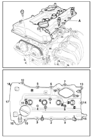
CAUTION
- Do not reuse cylinder head cover gasket.
- The tiring and/or blow out test should not be performed within 30 minutes after the cylinder head cover was assembled.
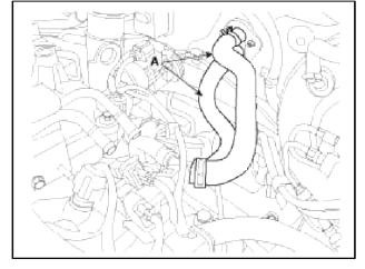
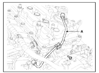
17. Connect the oil cooler coolant hoses (A).
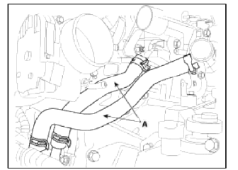
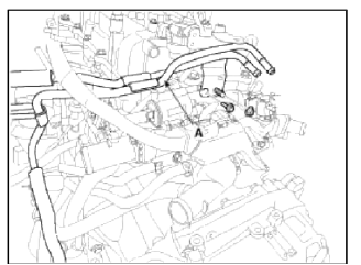
18. Connect the throttle body coolant hoses (A).
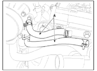
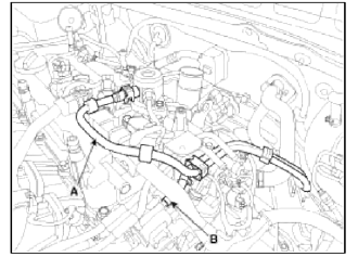
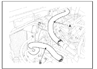
19. Connect the heater hoses (A).
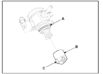
20. Install the high pressure fuel pump (A) and the roller tappet (B). (Refer to FL group)
Tightening torque : 12.7 ~ 14.7N.m (1.3 ~ 1.5kgf.m, 9.4 ~ 10.8lb-ft)
CAUTION
Before installing the high pressure fuel pump, position the roller tappet in the lowest position (BDC) by rotating the crankshaft. Otherwise the installation bolts may be broken because of tension of the pump spring.
NOTE
Do not use already used bolt again.
NOTE
When tightening the installation bolts of the high pressure fuel pump, tighten in turn the bolts in small step (0.5 turns) after tightening them with hand-screwed torque.
CAUTION
Note that internal damage may occur when the component is dropped. In this case, use it after inspecting.
NOTE
Apply engine oil to the О-ring (A) of the high pressure fuel pump, the roller tappet (B), and the protrusion (C). Also apply engine oil to the groove where the protrusion is installed.
21. Install the high pressure pipe (A). (Refer to FL group)
Tightening torque:
Bolt: 7.8 ~ 11.8N.m (0.8 ~ 1.2kgf.m, 5.8 ~ 8.7lb-ft)
Nuts : 26.5 ~ 32.4N.m (2.7 ~ 3.3kgf.m, 19.5 ~ 23.9lb-ft)
NOTE
Do not reuse the high pressure pipe.
22. Install the vacuum pipe assembly (A).
Tightening torque: Bolt & nut: 7.8 ~ 9.8N.m (0.8 ~ 1.0kgf.m, 5.8 ~ 7.2lb-ft)
23. Connect the fuel hose (A) and PCSV (Purge control solenoid valve) hose (B).
24. Connect the wiring connectors and harness clamps, and install the wiring protectors to the cylinder head, intake manifold and exhaust manifold.
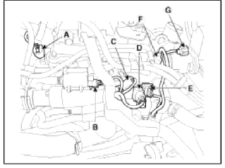
- Connect the exhaust OCV (Oil control valve) connector (A) and the oxygen sensor connector (B).
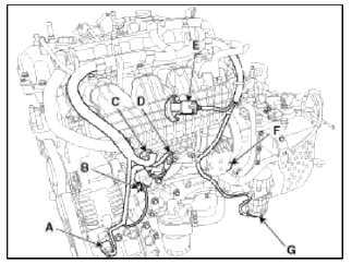
- Connect the Ð/С compressor switch connector (A), the alternator connector (B), the OPS (Oil pressure switch) connector & injector extension connector (C), the knock sensor connector (D), the MAPS (Manifold absolute pressure sensor) & IATS (Intake air temperature sensor) connector (E), the ETC (Electronic throttle control) connector (F) and the vacuum pump connector (G).
- Connect the PCV hose (A), the intake OCV (Oil control valve) connector (B) and the OTS (Oil temperature sensor) connector (C).
- Connect the ignition coil connectors (B) and the fuel pump connector (A).
- Connect the intake CMPS (Camshaft position sensor) connector (A), the PCSV (Purge control solenoid valve) connector (B), the ECTS (Engine coolant temperature sensor) connector (C), the condenser connector (D), the CKPS (Crankshaft position sensor) connector (E), the exhaust CMPS (Camshaft position sensor) connector (F) and the electric wastegate actuator connector (G).
25. Connect the radiator upper hose (A) and lower hose (B).
26. Install the under cover.
27. Remove the RH front wheel.
28. Install the intercooler inlet/outlet hoses and the air cleaner assembly. (Refer to Engine and transaxle assembly in this group)
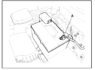
29. Connect the battery negative terminal (A).
Tightening torque: 4.0 ~ 6.0N.m (0.4 ~ 0.6kgf.m, 3.0 ~ 4.4lb-ft)
30. Install the engine cover.
Perform the following:
- Adjust a shift cable.
- Refill engine with engine oil.
- Refill a transaxle with fluid.
- Refill a radiator and a reservoir tank with engine coolant.
- Clean battery posts and cable terminals and assemble.
- Inspect for fuel leakage.
- After assemble the fuel line, turn on the ignition switch (do not operate the starter) so that the fuel pump runs for approximately two seconds and fuel line pressurizes.
- Repeat this operation two or thee times, then check for fuel leakage at any point in the fuel line.
- Bleed aft from the cooling system.
- Start engine and let it run until it warms up. (until the radiator fan operates 3 or 4 times.)
- Turn Off the engine. Check the level in the radiator, add coolant if needed. This will allow trapped air to be removed from the cooling system.
- Put radiator cap on tightly, then run the engine again and check for leaks.
READ NEXT:
 Components and ComponentsLocation | Disassembly - Repair procedures
Components
Piston ring
Snap ring
Piston
Connecting rod
Connecting rod upper bearing
Piston pin
Connecting rod lower bearing
Connecting rod bearing cap
SEE MORE:
Instrument panel overview/Engine compartment
Instrument panel overview
Audio remote control button
Driver's front air bag
Horn
Driving Assist button
Instrument cluster
Light control/turn signals lever
Wiper and washer control lever
Infotainment system
Hazard warning flasher switch
Climate control system/
Reverse Parking Distance Warning settings
Reverse Parking Distance Warning will
help warn the driver if a person, an animal
or an object is detected within a certain
distance when the vehicle is moving
in reverse.
Detecting sensor
Rear ultrasonic sensors
Refer to the picture above for the
detailed location of the detecting senso
Content
- Home
- Kia Sportage - Fifth generation (NQ5) - (2022-2026) - Owner's Manual
- Kia Sportage - Second generation (JEKM) (2005-2015) - Body Workshop Manual
- Kia Sportage Third generation (SL) - (2011-2016) - Service and Repair Manual
- Sitemap
- Top articles
