Kia Sportage: Inspection - Repair procedures - Cylinder Head
Inspection
Cylinder Head
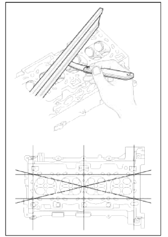
1. Inspect for flatness.
Using a precision straight edge and feeler gauge, measure the surface the contacting the cylinder block and the manifolds for warpage.
Flatness of cylinder head gasket surface
Standard : Less than 0.05mm (0.0019in.) for total area
Less than 0.02mm (0.0007in.) for a section of l00mm (3.9370in.) X 100mm (3.9370in.)
Flatness of manifold mounting surface (Intake/Exhaust)
Standard : Less than 0.10mm (0.0039in.)
2. Inspect for cracks.
Check the combustion chamber, intake ports, exhaust ports and cylinder block surface for cracks. If cracked, replace the cylinder head.
Valve And Valve Spring
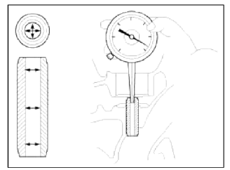
1. Inspect valve stems and valve guides.
- Using a caliper gauge, measure the inside diameter of the valve guide.
Valve guide inner diameter
Intake / Exhaust: 5.500 ~ 5.512mm (0.21654 ~ 0.21701in.)
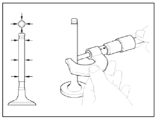
- Using a micrometer, measure the diameter of the valve stem.
Valve stem outer diameter
Intake: 5.465 ~ 5.480mm (0.21516 ~ 0.21575in.)
Exhaust: 5.458 ~ 5.470mm (0.214988 ~ 0.21535in.)
- Subtract the valve stem diameter measurement from the valve guide inside diameter measurement.
Valve stem-to-guide clearance
[Standard]
Intake: 0.020 ~ 0.047mm (0.00078 ~ 0.00185in.)
Exhaust: 0.030 ~ 0.054mm (0.00118 ~ 0.00212in.)
[Limit]
Intake: 0.070mm (0.00275in.)
Exhaust: 0.090mm (0.00354in.)
If the clearance is greater than maximum, replace the valve or cylinder head.
2. Inspect the valves.
- Check the valve is ground to the correct valve face angle.
- Check that the surface of the valve for wear.
If the valve face is worn, replace the valve.
- Check the valve head margin thickness.
Valve head thickness (Margin)
[Standard]
Intake: 1.02mm(0.0401in.)
Exhaust: 1.09mm(0.0429in.)
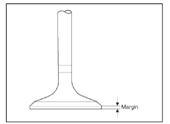
If the margin thickness is less than minimum, replace the valve.
- Check the valve length
Valve length
[Standard]
Intake : 113.18mm(4.4559in.)
Exhaust: 105.84mm(4.1669in.)
[Limit]
Intake : 112.93mm(4.4461in.)
Exhaust: 105.59mm(4.1571in.)
- Check the surface of the valve stem tip for wear.
If the valve stem tip is worn, replace the valve.
3. Inspect the valve seats
- Check the valve seat for evidence of overheating and improper contact with the valve face. Replace the cylinder head if necessary.
- Check the valve guide for wear. If the valve guide is worn, replace the cylinder head.
4. Inspect the valve springs.
- Using a steel square, measure the out-of-square of the valve spring.
- Using a vernier calipers, measure the free length of the valve spring
Valve spring
[Standard]
Free height: 47.44mm (1.8677in.)
Out-of-square : Less than 1.5º
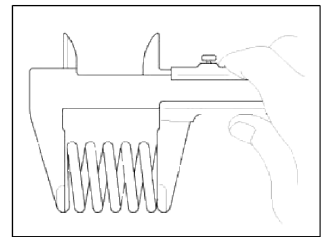
If the free length is not as specified, replace the valve spring.
MLA (Mechanical Lash Adjuster)
1. Inspect the MLA.
Using a micrometer, measure the MLA outside diameter.
MLA outer diameter: 31.964 ~ 31.980mm (1.2584 ~ 1.2590in.)
2. Using a caliper gauge, measure MLA tappet bore inner diameter of cylinder head.
Tappet bore inner diameter : 32.000 ~ 32.025mm (1.2598 ~ 1.2608in.)
3. Subtract MLA outside diameter measurement from tappet bore inside diameter measurement.
MLA to tappet bore clearance
[Standard] : 0.020 ~ 0.061mm (0.00078 ~ 0.00240in.)
[Limit]: 0.070mm (0.00275in.)
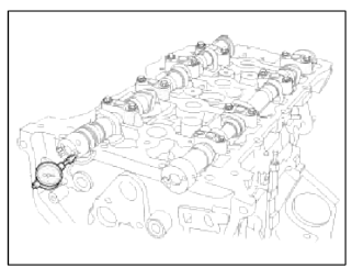
Camshaft
1. Inspect the Ñаm lobes.
Using a micrometer, measure the cam lobe height.
Cam height
[Standard value]
Intake : 44.10 ~ 44.30mm (1.7362 ~ 1.7440in.)
Exhaust: 44.90 ~ 45.10mm (1.7677 ~ 1.7756in.)
If the cam lobe height is less than standard, replace the camshaft.
2. Inspect the camshaft journal clearance.
- Clean the bearing caps and camshaft journals.
- Place the camshafts on the cylinder head.
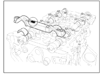
- Lay a strip of plastigage across each of the camshaft journal.
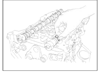
- Install the bearing caps.
CAUTION
Do not turn the camshaft.
- Remove the bearing caps.
- Measure the plastigage at its widest point.
Bearing oil clearance
[Standard value]
Intake:
No.1 : 0.022 ~ 0.057mm (0.00087 ~ 0.00224in.)
No.2, 3, 4, 5 : 0.045 ~ 0.082mm (0.00177 ~ 0.00323in.)
Exhaust:
No.1 : 0 ~ 0.032mm (0 ~ 0.00126in.)
No.2, 3, 4, 5 : 0.045 ~ 0.082mm (0.00177 ~ 0.00323in.)
[Limit]
Intake:
No.1 : 0.090mm (0.00354in.)
No.2, 3, 4, 5 : 0.120mm (0.00472in.)
Exhaust:
No.1 : 0.090mm (0.00354in.)
No.2, 3, 4, 5 : 0.120mm (0.00472in.)
If the oil clearance is greater than maximum, replace the camshaft. If necessary, replace cylinder head.
- Completely remove the plastigage.
- Remove the camshafts.
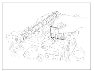
3. Inspect the camshaft end play.
- Install the camshafts.
- Using a dial indicator, measure the end play while moving the camshaft back and forth.
Camshaft end play
[Standard value]: 0.04 - 0.16mm (0.0016 - 0.0063in.)
[Limit]: 0.20mm (0.0078in.)
If the end play is greater than maximum, replace the camshaft. If necessary, replace cylinder head.
- Remove the camshafts
Exhaust Camshaft Bearing
1. Check the cylinder head bore mark.
Cylinder Head Bore Identification Mark
Cylinder Head Specifications
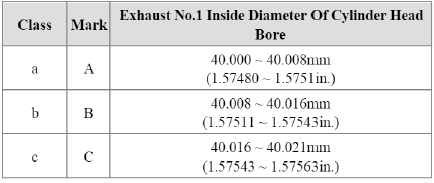
2. Select class of camshaft bearing same as class of cylinder head as shown on the table below.
Exhaust Camshaft Bearing Identification Mark
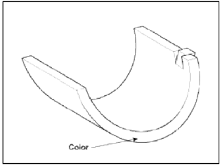
Exhaust Camshaft Bearing Specifications
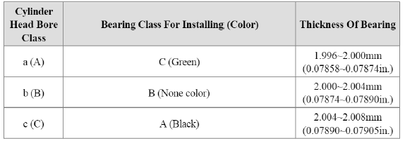
Oil clearance : 0 ~ 0.032mm (0 ~ 0.00126in.)
CVVT Assembly
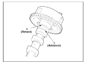
1. Inspect CVVT assembly.
- Check that the CVVT assembly will not turn.
- Apply vinyl tape to the retard hole except the one indicated by the
arrow in the illustration.
Verify the hold to tape and the hole to put air in.
[Intake]
![[Exhaust]](images/books/1921/18/index%20126.png)
[Exhaust]
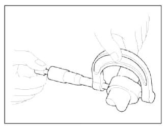
- Wind tape around the tip of the air gun and apply air of approx. 150kPa
(1.5kgf/cm2,21psi) to the port of the
camshaft.
(Perform this in order to release the lock pin.)
NOTE
When the oil splashes, wipe it off with a shop rag and the likes.
- With air applied, as in step (3), turn the CVVT assembly to the advance
angle side (the arrow marked
direction in the illustration) with your hand.
Depending on the air pressure, the CVVT assembly will turn to the advance side without applying force by hand. Also, under the condition that the pressure can be hardly applied because of the air leakage from the port, there may be the case that the lock pin could be hardly released.
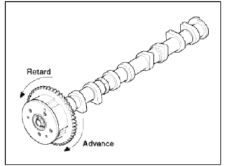
- Turn the CVVT assembly back and forth and check the movable range and that there is no disturbance.
Standard:
Should move smoothly in a range from about
22.5º (Intake) / 20.0º (Exhaust)
- Turn the intake CVVT assembly with your hand and lock it at the maximum retard angle position (counter clockwise).
- Turn the exhaust CVVT assembly with your hand and lock it at the maximum advance angle position (clockwise).
Reassembly
NOTE
Thoroughly clean all parts to be assembled.
Before installing the parts, apply fresh engine oil to all sliding and rotating surfaces.
Replace oil seals with new ones.
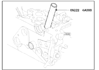
1. Install valves.
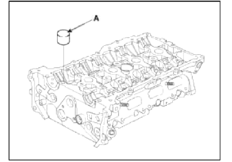
- Using SST (09222-4A000), push in a new oil seal.
NOTE
Do not reuse old valve stem seals.
Incorrect installation of the seal could result in oil leakage past the valve guides.
- Install the valve, valve spring and spring retainer.
NOTE
Place valve springs so that the side coated with enamel faces toward the valve spring retainer and then installs the retainer.
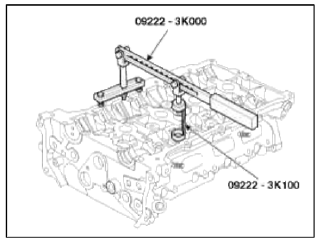
- Using the SST (09222-3K000, 09222-3K100), compress the spring and install the retainer locks. After installing the valves, ensure that the retainer locks are correctly in place before releasing the valve spring compressor.
- Lightly tap the end of each valve stem two or three times with the wooden handle of a hammer to ensure proper seating of the valve and retainer lock.
2. Install the MLAs after appling engine oil.
Check that the MLA rotates smoothly by hand.
NOTE
MLA can be reinstalled in its original position.
However, the valve lash clearances must be rechecked and adjusted accordingly before the cylinder head is installed onto the cylinder block.
Refer to General information in EM section for Valve Clearance checking and adjustment procedure.
READ NEXT:
 Installation - Repair procedures - Cylinder Head
Installation
NOTE
Thoroughly clean all parts to be assembled.
Always use a new head and manifold gasket.
The cylinder head gasket is a metal gasket. Take care not to bend it.
Rotate the cra
Components and ComponentsLocation | Disassembly - Repair procedures
Components
Piston ring
Snap ring
Piston
Connecting rod
Connecting rod upper bearing
Piston pin
Connecting rod lower bearing
Connecting rod bearing cap
SEE MORE:
Low tire pressure telltale
Low tire pressure telltale
Low tire pressure position telltale
When the TPMS warning indicators are
appeared, one or more of your tires is
significantly under-inflated.
Low tire pressure
If the telltale illuminates, immediately
reduce your speed, avoid hard cornering
and anticipate
Description and Operation
Limitations Of The Navigation system
GPS Signal Reception State
As the GPS satellite frequency is received/transmitted in straight lines,
reception may not work if hiding devices are
placed on or near the GPS antenna or when traveling though the following
locations.
Tunnels
Content
- Home
- Kia Sportage - Fifth generation (NQ5) - (2022-2026) - Owner's Manual
- Kia Sportage - Second generation (JEKM) (2005-2015) - Body Workshop Manual
- Kia Sportage Third generation (SL) - (2011-2016) - Service and Repair Manual
- Sitemap
- Top articles
