Kia Sportage: Disassembly
Measuring dimensions before beginning
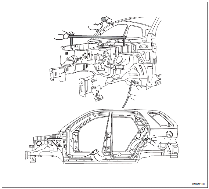
Measure the dimensions of the damaged area according to the body dimension drawings before disassembling and repairing. Adjust dimensions with body frame adjuster if deformed.
Selecting cutting area
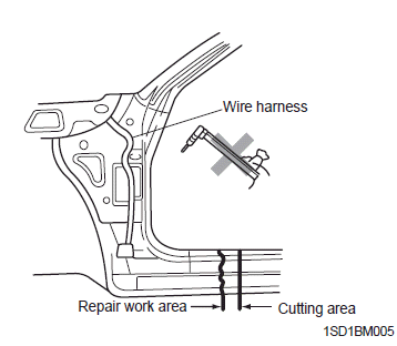
Select a cutting area that is easily accessible and that is prone to the least amount of distortion when welding.
Select an area that would allow the new part to overlap repair area by 1.2~2.0 in (30~50 mm).
Protecting body from damage
Secure the body with clamps and jacks to prevent damage to the body when working on it.
Disassembling related parts
Use caution when removing body molding and trim from the area to be worked. Apply masking tape where needed to prevent damage to the part being removed or to the vehicle body. Before starting repairs, check if pipes, hoses or electrical components are present near damaged area.
READ NEXT:
 Preparation of assembly
Applying spot sealer
Remove paint from the surface of new parts and body to be spot welded, and
apply spot sealer for rustproofing.
Selecting a welding method
If the thickness of the area to be w
Assembly
Measuring dimensions before welding
When assembling a new part, assemble it according to the body dimensions
given in Section 31, and start welding
after checking the gaps with nearby parts.
Caut
Rustproof treatment after assembly
Body sealing
Apply body sealer where necessary.
Applying rustproof material
Apply rustproofing material (wax, oil, etc.) behind welded area.
Applying undercoat
Apply undercoat on the body where
SEE MORE:
Components and ComponentsLocation | Repair procedures
Component location
Coupling
Sub frame
Assist arm
Lower arm
Upper arm
Trailing arm
Coil spring
Shock absorber
Stabilizer
Drive shaft
Differential carrier assembly
Components
Lock nut
Tone wheel
Ð’J as
Water pump
Components and Components Location
Components
Water pump pulley
Water pump sub assembly
Water pump gasket
Water pump cover
Water pump cover gasket
O-ring
Water inlet pipe
Water temperature control assembly
Water inlet fitting
Engine coolant temperature sensor
Thermos
Content
- Home
- Kia Sportage - Fifth generation (NQ5) - (2022-2026) - Owner's Manual
- Kia Sportage - Second generation (JEKM) (2005-2015) - Body Workshop Manual
- Kia Sportage Third generation (SL) - (2011-2016) - Service and Repair Manual
- Sitemap
- Top articles
