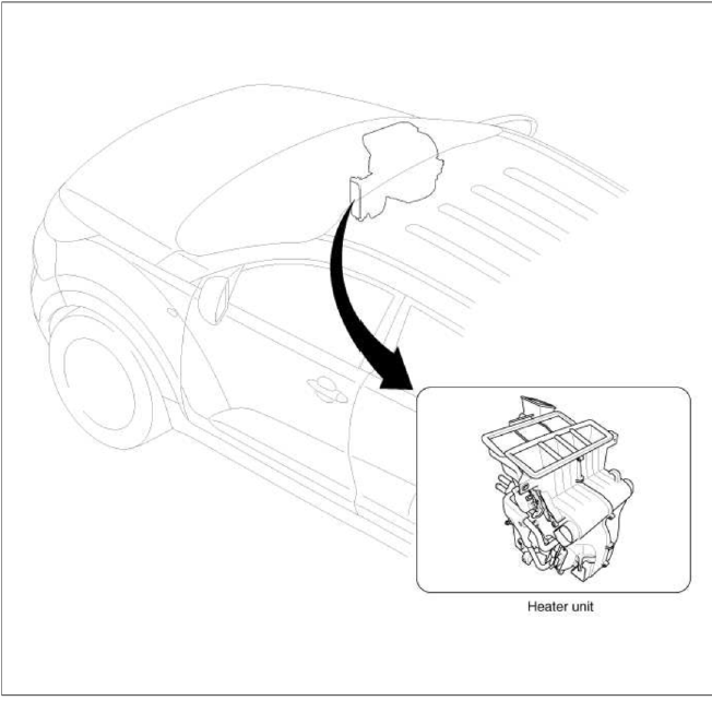
Kia Sportage: Heater Unit
Components and Components Location
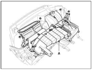
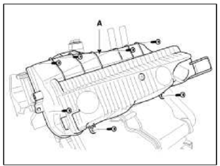
Component Location
Components
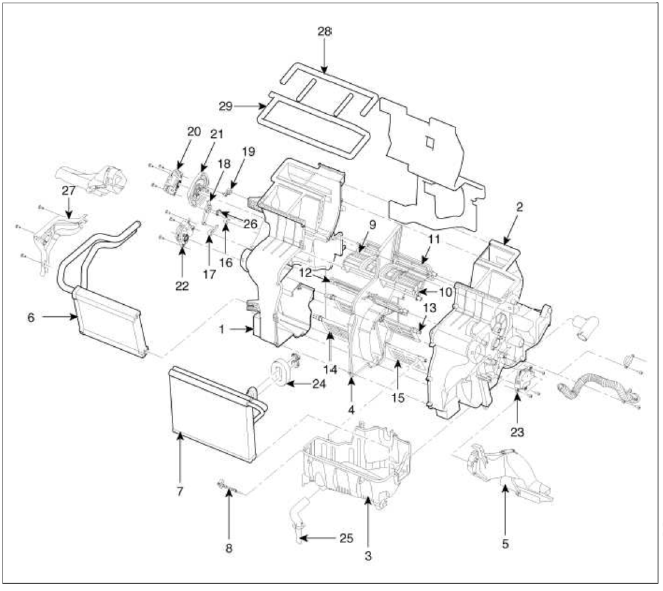
- Heater Case (LH)
- Heater Case (RH)
- Heater Lower Case
- Separator
- Shower Duct
- Heater Core
- Evaporator Core
- Evaporator Sensor
- Vent Door
- Vent Door
- Def Door
- Foot Door
- Temp Control Door
- Temp Control Door
- Temp Control Door
- Vent Door Arm
- Foot Lever
- Foot Door Arm
- Def Lever
- Mode Control Actuator
- Mode Cam
- Temp Control Actuator
- Temp Control Actuator
- Flange Seal
- Dram Hose
- Washer Spring
- Heater Core Cover
- Flange Seal
- Flange Seal
Repair procedures
Replacement
1. Disconnect the negative (-) battery terminal.
2. Recover the refrigerant with a recovery/ recycling/ charging station.
3. When the engine is cool, drain the engine coolant from the radiator.
4. Remove the expansion valve cover (A).
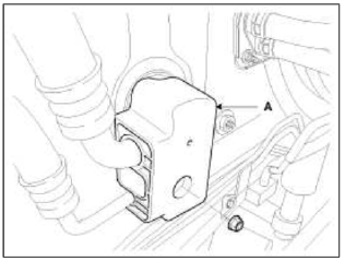
5. Remove the bolts (A) and the expansion valve (B) from the evaporator core.
Tightening torque: 7.8 ~ 11.7 N.m ( 0.8 ~ 1.2 kgf.m. 5.7 ~ 8.6 lb-ft)
CAUTION
Plug or cap the lines immediately after disconnecting them to avoid moisture and dust contamination.
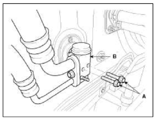
6. Remove the expansion valve flange (A).
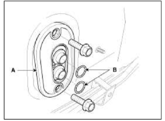
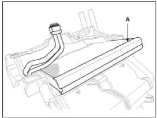
7. Disconnect the inlet (C) and outlet (D) heater hoses from the heater unit.
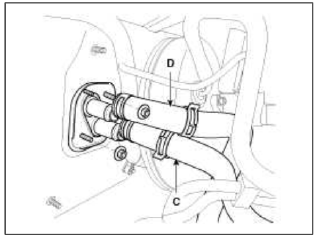
CAUTION
Engine coolant will run out when the hoses are disconnected; drain it into a clean drip pan. Be sure not to let coolant spill on electrical parts or painted surfaces. If any coolant spills, rinse it off immediately.
8. Remove the cowl top cover.
(Refer to BD group - "Cowl Top Cover").
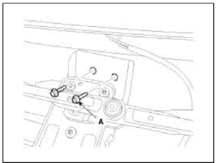
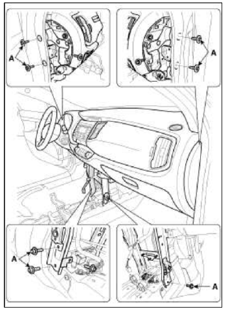
9. Loosen the cowl cross member mounting bolts (A).
10. Remove the steering handle and column.
(Refer to ST group - "Steering Column")
11. Remove the center console.
(Refer to BD group - "Center Console")
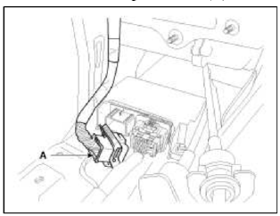
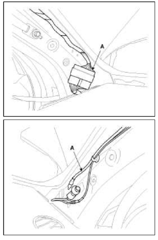
12. Disconnect the airbag connector (A).
13. Disconnect the connectors and then remove the left & right multi box (A).
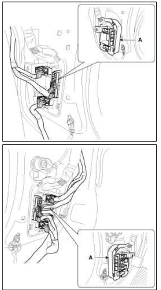
14. Remove the left & right filler trim and than disconnect the connector (A).
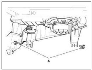
15. Remove the heater & blower unit after loosening mounting bolts (A).
16. Loosen the cowl cross member mounting bolts (A) and then remove the crash pad and heater blower unit.
17. Disconnect the connectors and then remove the heater blower unit (A) from crash pad.
18. Remove the blower unit (A) from heater unit (B) after loosening screws.
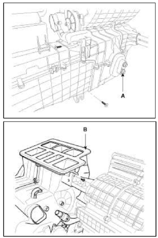
19. Loosen the mounting screw and then remove the heater core cover (A).
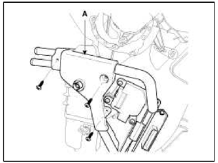
20. Disconnect the heater core (A) from heater unit.
21. Loosen the heater unit lower case mount screw and then remove the heater unit lower case (A).
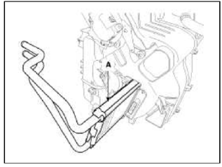
22. Remove the evaporator core (A).
23. Be careful that the inlet and outlet pipe are not bent during heater core removal, and pull out the heater core.
24. Installation is the reverse order of removal.
25. Installation is the reverse order of removal, and note these items:
- If you're installing a new evaporator, add refrigerant oil (ND-OIL8).
- Replace the O-rings with new ones at each fitting, and apply a thin coat of refrigerant oil before installing them. Be sure to use the right О-rings for R-134a to avoid leakage.
- Immediately after using the oil, replace the cap on the container, and seal it to avoid moisture absorption.
- Do not spill the refrigerant oil on the vehicle; it may damage the paint; if the refrigerant oil contacts the paint, wash it off immediately
- Apply sealant to the grommets.
- Make sure that there is no air leakage.
- Charge the system and test its performance.
- Do not interchange the inlet and outlet heater hoses and install the hose clamps securely.
- Refill the cooling system with engine coolant.
READ NEXT:
 Temperature Control Actuator
Components and
Components Location
Component Location
Description and
Operation
Description
1. Heater unit includes mode control actuator and temperature control
actuator.
2.
Mode Control Actuator
Components and
Components Location
Component Location
Description and Operation
Description
The mode control actuator is located at the heater unit.
It adjusts position of mode d
SEE MORE:
Battery saver function
This vehicle is equipped with a variety of
lights to illuminate the interior and exterior
of the vehicle.
CAUTION
To prevent the battery from being discharged,
do not leave the headlamp and
interior light on for a prolonged time
while the engine is not running.
Battery saver function
The pu
Scheduled maintenance service
Scheduled maintenance service precaution
Follow the Normal Maintenance Schedule
if the vehicle is usually operated
where none of the following conditions
apply. If any of the following conditions
apply, follow the Maintenance Under
Severe Usage Conditions.
Repeated driving short distance o
Content
- Home
- Kia Sportage - Fifth generation (NQ5) - (2022-2026) - Owner's Manual
- Kia Sportage - Second generation (JEKM) (2005-2015) - Body Workshop Manual
- Kia Sportage Third generation (SL) - (2011-2016) - Service and Repair Manual
- Sitemap
- Top articles
